T8635L MICROELECTRONIC COMMUNICATING PROGRAMMABLE THERMOSTAT
69-1331—5 2
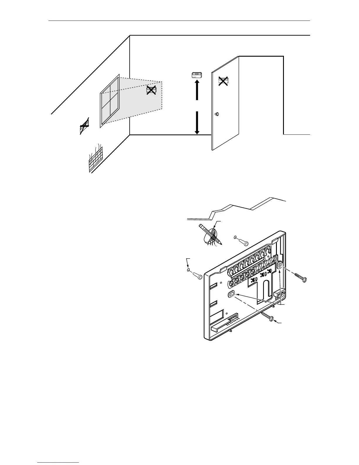
Fig. 1. Selecting thermostat location.
Do not install the thermostat where it can be affected by:
— drafts or dead spots behind doors and in corners.
— hot or cold air from ducts.
— radiant heat from sun or appliances.
— concealed pipes and chimneys.
— unheated (uncooled) areas such as an outside wall
behind the thermostat.
Wallplate Installation
The thermostat can be mounted horizontally on the wall
or on a 2 in. by 4 in. wiring box. Position wallplate hori-
zontally on the wall or on a 2 in. by 4 in. wiring box.
1. Position and level the wallplate (for appearance
only). The thermostat functions properly even
when not level.
2. Use a pencil to mark the mounting holes. See
Fig. 2.
3. Remove the wallplate from the wall and drill two
3/16-in. holes in the wall (if drywall) as marked.
For firmer material such as plaster, drill two
7/32-in. holes. Gently tap anchors (provided) into
the drilled holes until flush with the wall.
4. Position the wallplate over the holes, pulling the
wires through the wiring opening.
5. Loosely insert the mounting screws in the holes.
6. Tighten the mounting screws.
Fig. 2. Mounting the wallplate.
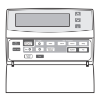
WIRING
All wiring must comply with local electrical codes and
ordinances. See Fig. 5 through 8 wiring diagrams for
specific equipment applications. Refer to Table 2 for ter-
minal designations.
5 FEET
[1.5 METERS]
YES
NO
NO
NO
M10106
WIRES
THROUGH WALL
WALL
MOUNTING
HOLES
MOUNTING
SCREWS
M6530A
WALL
ANCHORS
(2)
 Loading...