VISIONPRO® 8000 SMART THERMOSTAT
89 33-00096—04
Wiring guide — Wired Indoor Sensors
Electrical Interference (Noise) Hazard.
Can cause erratic system operation.
Keep wiring at least one foot away from large
inductive loads such as motors, line starters,
lighting ballasts and large power distribution
panels.
Use shielded cable to reduce interference when
rerouting is not possible.
IMPORTANT
Erratic temperature readings from a sensor can
occur as a result of any of the wiring practices
described below. Avoid these practices to assure
correct operation. Use shielded cable to reduce
interference if rerouting sensor wiring is not possi-
ble.
— Be sure wires have a cable separate from the ther-
mostat cable.
— Do not route temperature sensor wiring with build-
ing power wiring, next to control contactors or near
light dimming circuits, electric motors or welding
equipment.
— Avoid poor wiring connections.
— Avoid intermittent or missing building earth
ground.
Electrical Shock Hazard.
Can cause electrical shock or equipment damage.
Disconnect power supply before connecting wiring.
Use the S1 terminal for wired sensors.
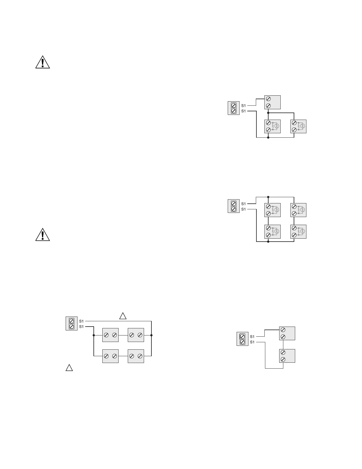
Wiring 4 C7189U1005 sensors (10k ohm) for temperature
averaging network. Select 10K in the Installer Setup (ISU
503) when using C7189U1005 sensor(s).
Fig. 231. Wiring 4 C7189U sensors.
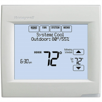
Wiring 2 TR21 sensors (20k ohm) and 1 TR21-A sensor
(10k ohm) for temperature averaging network. Select 20K
in the Installer Setup (ISU 503) when using 2 TR21 sensors
and 1 TR21-A sensor.
Fig. 232. Wiring 2 TR21 sensors and 1 TR21-A sensor.
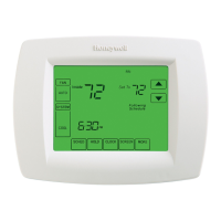
Wiring 4 TR21 sensors (20k ohm). Select 20K in the
Installer Setup (ISU 503) when using TR21 sensor(s).
Fig. 233. Wiring 4 TR21 sensors.
Wiring 2 TR21-A sensors (10k ohm) for temperature
averaging network. Select 20K in the Installer Setup (ISU
503) when using 2 TR21-A sensors in series. Note: The
TR21-A sensor must be used in combination with TR21 or
TR21-A sensor.
Fig. 234. Wiring 2 TR21-A sensors.
C7189 C7189
C7189 C7189
M35676
THE NUMBER OF C7189U SENSORS MUST BE
A SQUARE NUMBER (1, 4, 9, 16, ETC.)
1
1
M35677
TR21-A
T3
T4
TR21 TR21
M35679
TR21-A
T3
T4
TR21-A
T3
T4