MASTERTROL® AUTOMATIC BALANCING SYSTEM™ (MABS®) EZ ZONE (EZ-2 AND EZ-4) CONTROL PANELS
69-1360–2 10
LED Indicators
The panel features several LED status indicators visible
through a window in the cover. See Table 6.
Re-Booting the Microprocessor
When conditions hang up the microprocessor, press and
release the Boot button to re-boot the system and enter the
Purge mode.
ZoneMAX Sensor Leaving Air Temperature Sensor
The ZMS (not included) is a duct-mounted temperature probe
that monitors the supply of air temperature to control capacity
and prevent over-heating or coil icing. The sensor attaches to
the TL terminals at the upper left corner of the panel. See Fig.
9.
IMPORTANT
The ZMS wires must be at least 12 in. away from line
voltage wiring to ensure correct operation. When not
possible, shielded cable must be used.
ZoneMAX Sensor Configuration
DIP switches 2 and 3 set the ZoneMAX Sensor temperature
limit. See Table 7. The recommended setting for fossil fuel/
heat pump systems is 160°F (71°C). For heat pump systems,
the recommended setting is 120°F (49°). The cooling
temperature limit can be set to 40°F (4°C) or 48°F (9°C).
OPERATION
If the system trips due to exceeding a high or low temperature,
the heating or cooling system shuts down and the fan
continues running to dissipate the conditioned air from the
plenum. If the low limit was tripped, the cool LED flashes
continuously until it resets. If the high limit was tripped, the
Heat LED flashes continuously until it resets.
The ZoneMAX Sensor resets and allows normal system
operation when the supply air temperature rises ten degrees
in cooling mode, or falls ten degrees in heating mode. The ten
degrees provide adequate time to prevent short cycling of the
unit.
Circuit Breaker Protection
A built-in thermal circuit breaker protects the panel against
shorts in the thermostat and damper wiring and the remote
occupied/unoccupied switch. It does not protect against shorts
in the HVAC equipment wiring into the panel.
OPERATION
None of the LEDs light when the circuit breaker tripped. The
fuse is a yellow square or rectangular disk located right of the
TR1 and TR2 terminals. If it is hot to touch, remove panel
power for ten seconds to allow the circuit breaker to cool off
and reset.
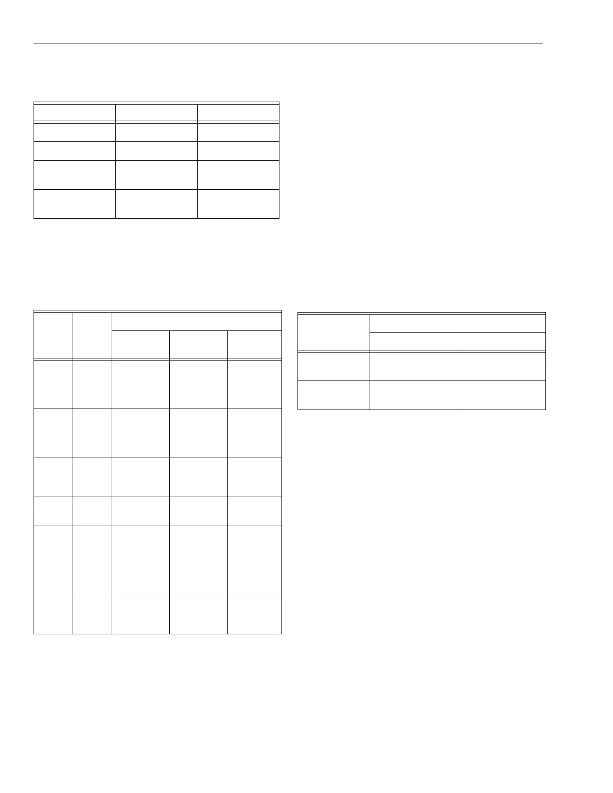
Table 5. Purge DIP switch settings.
DIP Switch No. Setting Action
1 Off 3.5 minutes
1 On 2 minutes
2 Off Panel control of
fan in Purge
2OnHVAC control of
fan in Purge
Table 6. LED Status Indicators.
LED Color
Status
Lighted
Not
Lighted Flashing
Heat Red Heat call Not in heat
call
ZMS high
temper-
ature limit
tripped
Cool Green Cool call Not in cool
call
ZMS low
temper-
ature limit
tripped
Purge Amber Purge
mode
Not in
Purge
mode
_
Fan Green Fan only
call
No fan only
calls
_
Em
Heat
Red Emergency
heat switch
on or ther-
mostat in
emergency
heat
Not in
emergency
heat mode
_
Zone
1,2,
3,4
Green Damper
open or
moving
Damper
closed
_
Table 7. ZoneMAX Sensor Configuration.
DIP Switch
No.
Setting
Off (Default) On
2 ZMS 160°F (71°C)
heating limit
ZMS 120°F (49°C)
heating limit
3 ZMS 40°F (4°C)
cooling limit
ZMS 48°F (9°C)
cooling limit
 Loading...