MASTERTROL® AUTOMATIC BALANCING SYSTEM™ (MABS®) EZ ZONE (EZ-2 AND EZ-4) CONTROL PANELS
69-1360–2 8
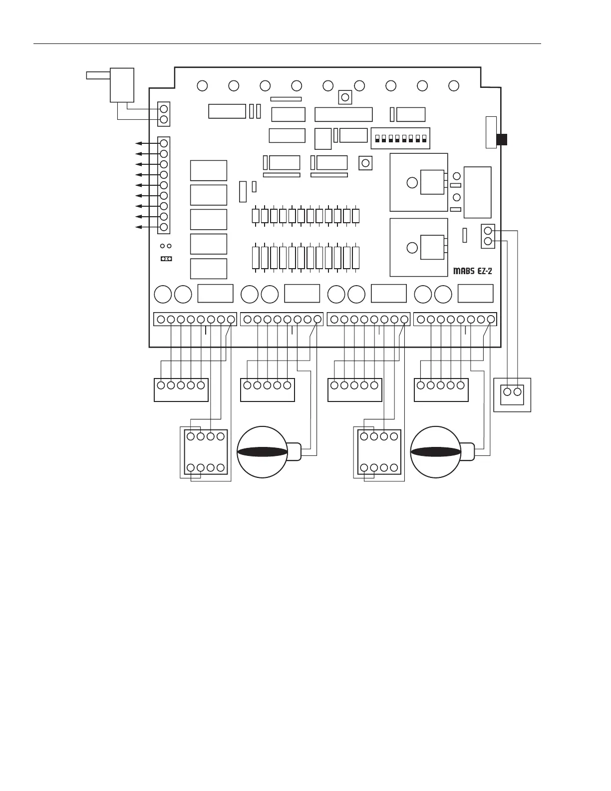
Fig. 15. MABS EZ-4 wiring diagram.
STARTUP AND CHECKOUT
After the installation is complete, verify the operation:
1. Put the Em Heat switch in the off (down) position.
2. Be sure the DIP switches are set correctly. See
Sequence of Operation and Table 6 for correct configu-
ration. The default position is in the off (down) position.
3. Power up the MABS EZ and set the thermostats so no
zones are calling. Verify that the board? enters the
Purge mode.
NOTE: During the two- or three and one-half- minute Purge,
the Purge LED should be amber. During this mode,
the dampers are open and the damper LEDs are
lighted green.
4. Set the zone one thermostat to heat and raise the set-
point to call for heat. The Heat LED is red and the zone
one damper remains green while the other damper
LEDs turn off.
5. Lower the setpoint in zone one and raise the setpoint in
zone two to call for heat. Verify that zone one LED turns
off (also zones three and four turn off when used on
MABS EZ-4) and zone two damper is green.
6. When using a MABS EZ-4, repeat for zones three and
four and verify correct operation.
7. Alternately, the setpoint can be lowered to call for cool-
ing. Then the green cool LED lights.
C
123X
4567
GYRWC
ZONE 2 THERMOSTAT
24V, 40 VA
TRANSFORMER
M19047A
AUTOMATIC ROUND DAMPER
POWERE CLOSED (ARD)
OPPOSED BLADE
DAMPERMOTOR
ZONE 1 THERMOSTAT
ZONE THERMOSTAT
ZONE DAMPERS
GYRW
THIS DIAGRAM SHOWS TYPICAL
SINGLE-STAGE THERMOSTAT
AND DAMPER MOTOR CONNECTIONS.
W2
E
W1
B
G
R
O
Y1
Y2
TL
TL
GL
ZONE 1
2ND STG. EMG.
THERMOSTAT MOTOR
YRWM6M4M1
CR
TR1
TR2
HEAT
SECOND STAGE COOLING RELAY
FIRST STAGE COOLING RELAY
REVERSING VALVE (COOLING)
24V TRANSFORMER (HOT)
FAN RELAY
REVERSING VALVE (HEATING)
FIRST STAGE HEATING
EMERGENCY HEAT RELAY
SECOND STAGE HEATING RELAY
HVAC CONTROLS
ZoneMAX
TM
COOL PURGE FAN EM.HT ZONE 1 ZONE 2 ZONE 3 ZONE 4
GRN - DAMPER OPEN/MOVING
OFF - DAMPER CLOSED
BOOT
PURGE
OVERRIDE
ON
OFF
EM HEAT
ON
1
LGYRWM6M4
M1
ZONE 2
THERMOSTAT MOTOR
2 3 4 5 6 7 8
C
123X
4567
GYRWC
ZONE 4 THERMOSTAT
AUTOMATIC ROUND DAMPER
POWERE CLOSED (ARD)
OPPOSED BLADE
DAMPERMOTOR
ZONE 3 THERMOSTAT
GYRW
GL
ZONE 1
THERMOSTAT MOTOR
YRWM6M4M1 LGYRWM6M4
M1
ZONE 2
THERMOSTAT MOTOR
OPTIONAL ZoneMAX
OR C7735 SUPPLY AIR
TEMPERATURE
SENSOR
TM
 Loading...