MASTERTROL® AUTOMATIC BALANCING SYSTEM™ (MABS®) EZ ZONE (EZ-2 AND EZ-4) CONTROL PANELS
69-1360–2 4
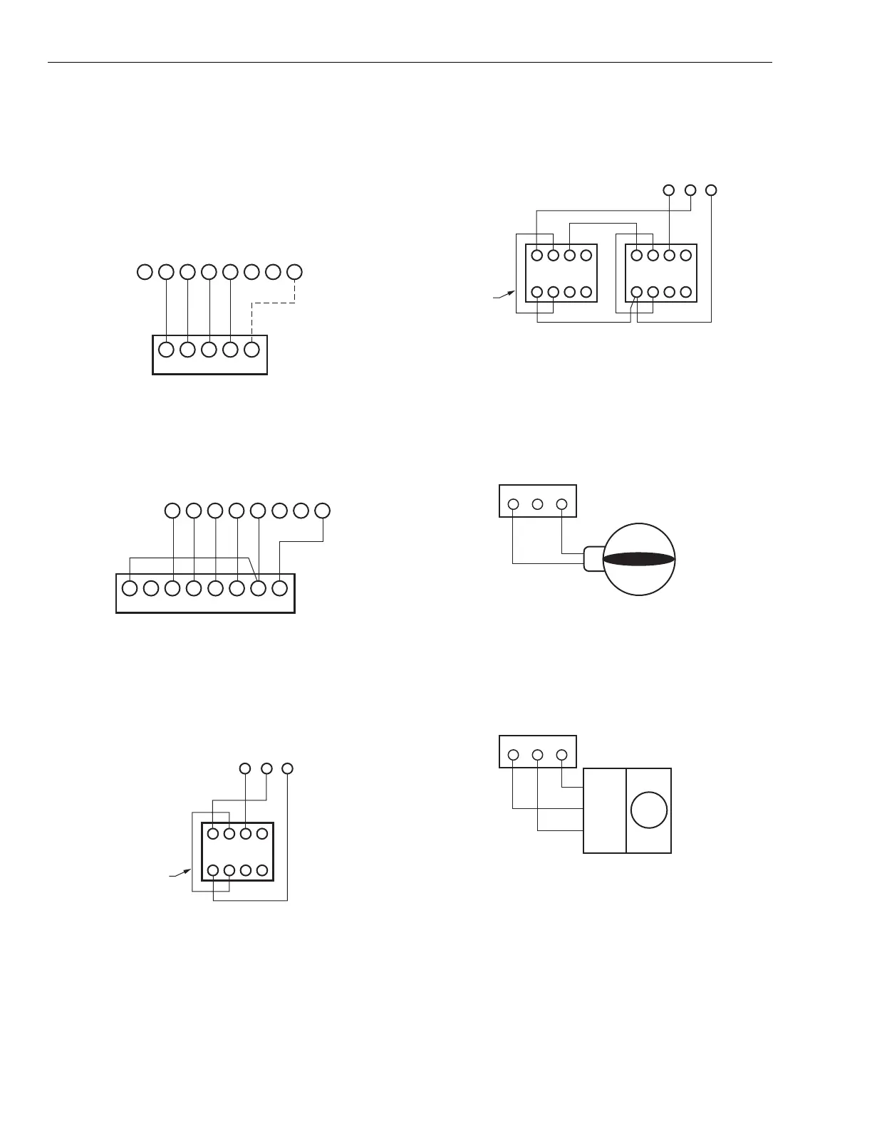
Wiring Diagrams
See Table 1 for recommended thermostats. See Fig. 1-15 for
wiring appropriate wiring diagrams.
NOTE: The common wire (C to M1) is used only on thermo-
stats that require it.
Fig. 1. Typical single-stage thermostat hookup diagram.
Fig. 2. Heat pump thermostats with separate heat and
cool outputs.
Use only thermostats listed in Table 1.
Fig. 3. AOBD damper wiring (single).
NOTE: Wiring is the same for AOBD, AOBD-BM and IOBD
Dampers.
Fig. 4. AOBD Damper wiring (multiple).
NOTE: For three or more AOBD dampers on one zone, a
Slave Damper Control Relay (SDCR) is required.
Fig. 5. ARD or ZD Damper wiring diagram.
NOTE: Multiple dampers can be wired in parallel, with up to
five dampers wired to each panel.
Fig. 6. MARD and CDO-51 Damper wiring diagram.
L G Y R W M6
GYRWC
M4 M1
THERMOSTAT
ZONE CONNECTIONS ON PANEL
ZONE THERMOSTAT
M19033
MOTOR
LGYR W M6
E W2 L G Y1 R W1 C/X
M4 M1
THERMOSTAT
ZONE CONNECTIONS ON PANEL
ZONE THERMOSTAT
M19034
MOTOR
4
M6 M4 M1
5 6
123
DAMPER MOTOR
FIELD JUMPER
M19035
MOTOR TERMINALS
4
M6 M4 M1
5 6
123
DAMPER MOTORS
M19036
MOTOR TERMINALS
4 5 6
123
FIELD
JUMPER
M6 M4 M1
M19037
DAMPER TERMINALS
ON PANEL
POWER CLOSE
SPRING OPEN
C MODEL ARD, ZDS, ZDB
M6 M4 M1
COM/M1
CL/M6
OP/M4
M19038
DAMPER TERMINALS
ON PANEL
 Loading...