MASTERTROL® AUTOMATIC BALANCING SYSTEM™ (MABS®) EZ ZONE (EZ-2 AND EZ-4) CONTROL PANELS
69-1360–2 6
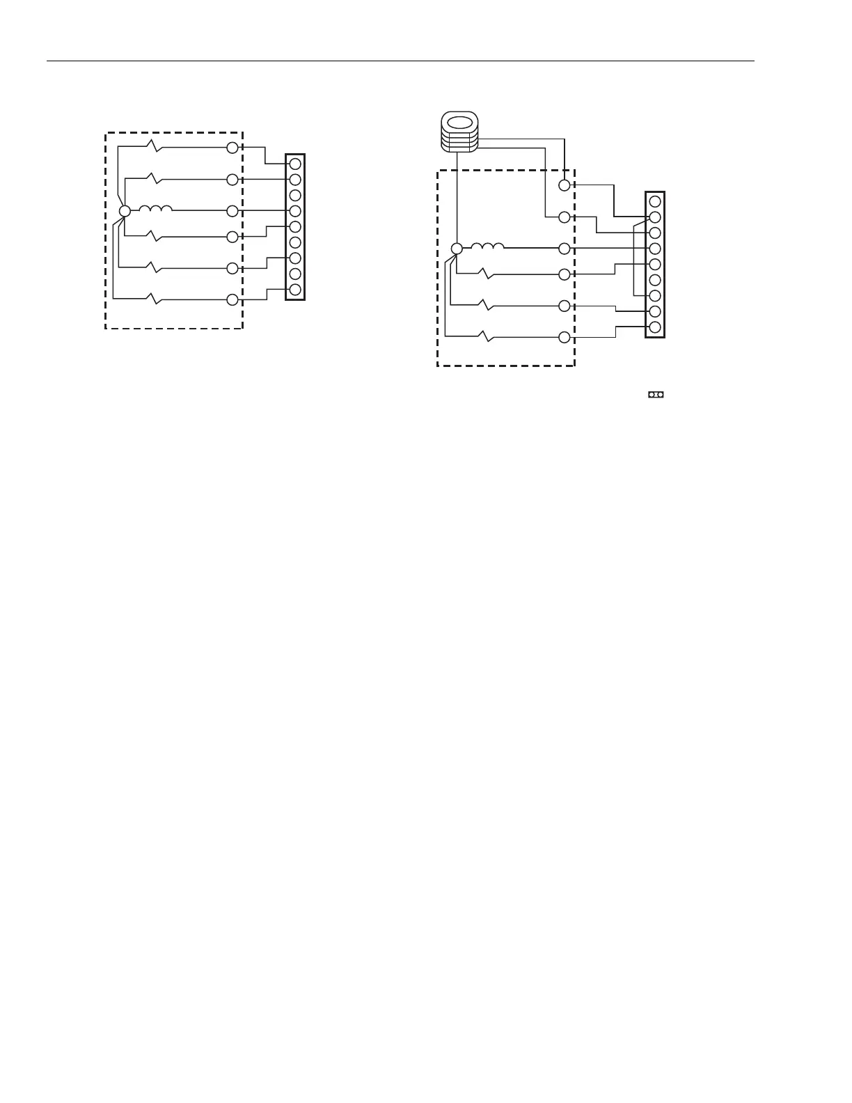
Fig. 12. Two-stage heating and cooling wiring diagram.
NOTE: The stage timer energizes the second stage equip-
ment.
Fig. 13. Heat pump wiring diagram.
IMPORTANT
Y1 must be jumped to W1 for compressor control.
Set DIP switch 8 to On to energize the fan with a call
for heat.
NOTES:
— Fossil Fuel Kits with Heat Pumps: The wiring for
these heat pumps is similar but the manufac-
turer's fossil fuel control must be used. The EZ
equipment terminals are wired using the thermo-
stat terminals shown on the heat pump manufac-
turer's wiring diagrams.
— Two-speed Compressors: For two-speed com-
pressors or two-speed compressors with auxiliary
heat, the EMM-3U or TotalZone panels are rec-
ommended. Call Honeywell Zoning at 800-828-
8367 for assistance.
W2
M19044
E
W1
W2
W1
B
G
R
24V TRANSFORMER
FAN RELAY
FIRST STAGE
COOLING RELAY
FIRST STAGE
HEATING RELAY
SECOND STAGE
HEATING RELAY
HVAC CONTROLS
MABS EZ
PANEL
R
C
Y1
G
O
Y1
Y2
SECOND STAGE
COOLING RELAY
Y2
W2
M19045A
E
W1
W2
E
B
G
R
24V TRANSFORMER
FAN RELAY
REVERSING
VALVE
FIRST STAGE
HEATING RELAY
SECOND STAGE
HEATING RELAY
DIP SWITCH
CONFIGURATION
NO. 8 - ON
HEAT PUMP CONTROLS
MABS EZ
PANEL
R
C
O
G
O
Y1
Y2
COMPRESSOR
RELAY
Y
OUTDOOR CONDENSING UNIT
COMPRESSOR RELAY
2 STAGE
EM. HT.
 Loading...