TZ-3 TOTALZONE® ZONE CONTROL PANEL
68-0223-2 10
On a call for heatin
or coolin
, the zone dam
er sta
s o
en
to the callin
zone, and the dam
ers close to the zones that
are not callin
. The TZ-3
anel brin
s on the heatin
or
coolin
and conditioned air is delivered to the callin
zone
until that zone is satisfied. When the call is satisfied, the
s
stem enters the Pur
e mode. This holds o
en the dam
er
of the last zone callin
and
ur
es into that zone. The
ur
e
time can be set to three and one-half or two minutes. After
ur
e, all dam
ers return to the O
en
osition.
An
zone thermostat can call for heatin
or coolin
. If there
are co-existin
calls for heat and cool, the
anel first acce
ts
the first call. Once that call is satisfied, or a maximum of 20
minutes has ela
sed, the
anel switches to allow the o
osite
call.
On a call for heatin
or coolin
, the heat LED illuminates red
or the cool LED illuminates
reen. The zone dam
er LED
turns
reen for the zone callin
, and the dam
ers in the zones
not callin
close and turn red. As AOBD dam
ers move, the
LEDs turn amber.
At the end of ever
call for heat or cool, the
anel enters a
Pur
e mode that holds o
en the callin
zone dam
er for three
and one-half or two minutes. Durin
this time, the
anel or the
HVAC e
ui
ment can o
erate the fan. Pur
e also serves as a
time dela
to
revent short c
clin
of the heatin
and coolin
e
ui
ment after each call. Pur
e LED li
hts to si
nal that the
s
stem is in the Pur
e mode. Pressin
the
ur
e override
button for two seconds overrides the Pur
e mode. Unless
there is a new call for heat or cool durin
the Pur
e mode, all
dam
ers are moved to the O
en
osition at the end of
ur
e.
Individual Zone Fan Control
When all zones are satisfied, the Fan switch of each
thermostat controls the fan o
eration for that zone. When the
Fan switch is in the On
osition, the fan is ener
ized, and the
dam
ers close to zones where the Fan switch is in the Auto
osition. If there is a call for heat or cool durin
this time, the
circulation mode ceases, and the heat or cool call is honored.
When the zone callin
is satisfied, the circulation call
resumes.
Single and Multi-Stage Operation
The
anel can control u
to three sta
es of heatin
and two
sta
es of coolin
. The first sta
e is ener
ized b
the
thermostat. The second sta
e of heatin
is brou
ht on b
the
thermostat, timer, or number of zones callin
. The third sta
e
of heatin
is brou
ht on b
the timer or number of zones
callin
. The second sta
e of coolin
is brou
ht on b
the timer
or number of zones callin
.
The followin
instructions show how to confi
ure the
anel for
sta
e control.
If the e
ui
ment is sin
le sta
e, set the DIP switches as
follows:
1st Stage by Thermostat, 2nd and 3rd Stages by
The thermostat controls the first sta
e of heat or cool. If the
call is not satisfied b
the first sta
e within the time set on the
timer, the
anel ener
izes the second sta
e. If the call for heat
is not satisfied b
the second sta
e within the time set on the
timer, the
anel brin
s on the third sta
e.
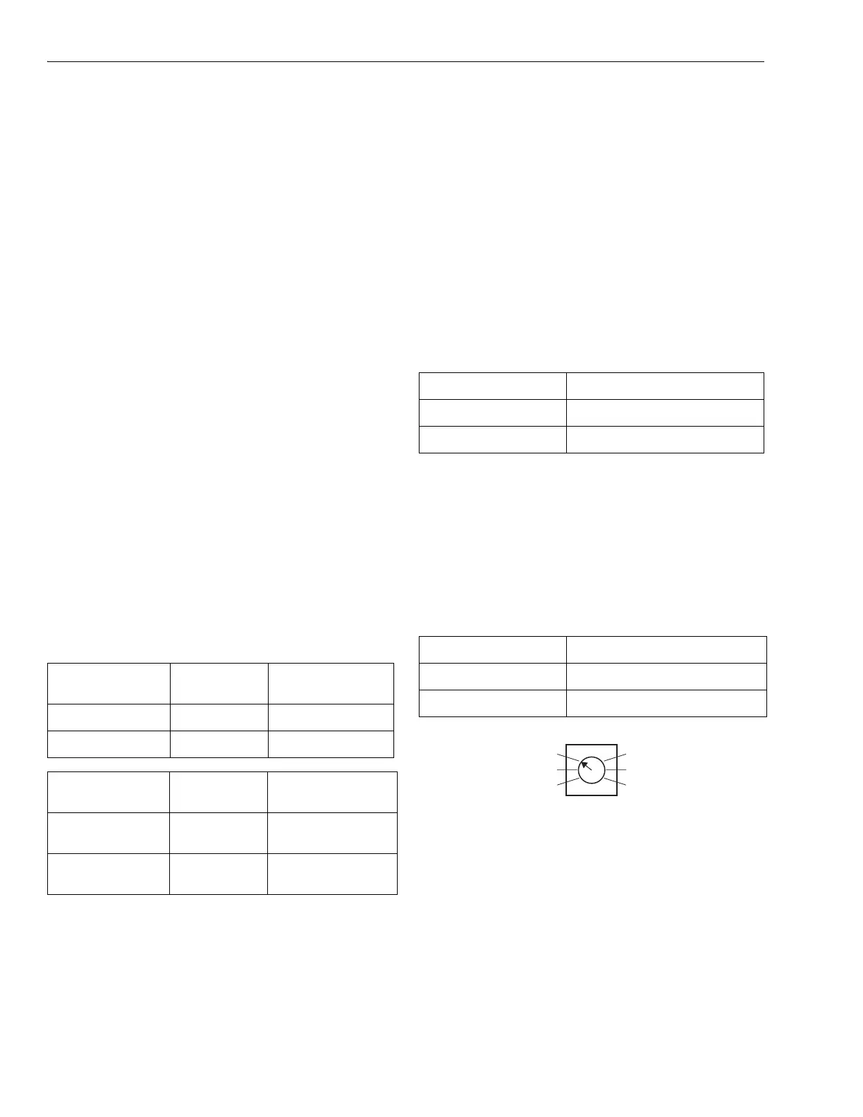
Set the DIP switches as follows:
Fig. 18. Stage timer.
1st Stage by Thermostat, 2nd Stage Heat by
The thermostat controls the first sta
e of heat or cool and the
second sta
e of heat. The timer controls the second sta
e of
cool and third sta
e of heat. If the first and second sta
es
combined do not satisf
the heat call within the time s
ecified
on the timer, the
anel brin
s on the third sta
e of heat.
Set the DIP switches as follows:
DIP Switch
Number Status Purge Time
3 Off 3.5 minutes
3 On 2 minutes
DIP Switch
Number
Status Fan Control
4 Off Panel control of fan
in
ur
e
4 On HVAC control of fan
in
ur
e
DIP Switch Number Status
1 Off
5 Off
DIP Switch Number Status
1 Off
5 Off
15 MINUTES
10 MINUTES
5 MINUTES
20 MINUTES
25 MINUTES
30 MINUTES
STAGE TIMER
M19078
 Loading...