Do you have a question about the Honeywell GX-Series and is the answer not in the manual?
Details the necessary terminal connections between the control panel and the keypad for initial setup.
Lists the default User, Engineer, and other essential codes for system access and operation.
Illustrates the overall system layout and connectivity of the control panel with peripherals.
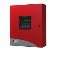
Step-by-step instructions for physically installing the main control cabinet securely.
Guide on how to fit and secure the lock mechanism to the control cabinet door.
Procedures for correctly installing and connecting the main power transformer to the control unit.
Instructions for establishing a connection to the public switched telephone network for communication.
Explains the required daisy-chain and twin AB daisy-chain wiring methods for RS485 communication.
Defines the default zone settings and addresses, including panel and RIO zone numbering.
Details how the RIO switch (SW3) controls on-board RIO addressing and ordering.
Provides guidance on the correct wiring methods for zone circuits, including double-balanced and end-of-line configurations.
Lists the on-board outputs, their addresses, default functions, types, ratings, and normal states.
Provides a table detailing the correct wiring connections between the GX-Series panel and its peripherals.
Outlines the valid addresses for connecting various peripherals to the GX-Series system.
Instructions for connecting the Remote Input Output (RIO) module to the GX-Series system via RS485.
Details the process of configuring the RIO module after connection, including checking communication status.
Describes the optional Ethernet module for alarm signaling and remote servicing over LAN/WAN.
Introduces the PC-based application for remote configuration, programming, and diagnostics of GX-Series systems.
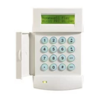
Details the features, power consumption, wiring, and installation of the Mk7 Keypad.
Details the wiring process for connecting GX-Series LCD keypads to the system.
Step-by-step guide for physically mounting and attaching the keypad to a wall.
Instructions for incorporating a new keypad into an existing GX-Series system, including address configuration.
Explains how to run diagnostic tests on the keypad to verify its operational status.
Step-by-step guide for physically installing the TouchCenter unit, including mounting and cable connection.
Details the process of setting an address and registering the TouchCenter with the control panel.
Describes the Door Control Module (DCM) and its role in adding access control functionality to the GX-Series bus.
Explains how to connect standard Wiegand card readers or keypads to the DCM for access control.
Details how to set the unique address for the DCM using its on-board DIP switches.
Instructions for wiring the DCM to the GX-Series RS485 bus line in a daisy-chain configuration.
Describes how users and engineers can access different levels of menu options based on their assigned codes.
Details how to enter and exit the engineer mode for system programming and advanced configuration.
Step-by-step guide on how users can arm the security system using a Personal Identification Number.
Procedures for disarming the security system using a valid user code and PIN.
Overview of features that assist users in setting and unsetting the system, minimizing errors.
Explains how to temporarily remove zones from system monitoring, preventing alarms.
Provides information on DCM readers, user access logs, and viewing access events.
Describes how to perform walk tests on zones to verify detector functionality and system response.
Covers assigning, modifying, and deleting user codes, PINs, and card access details.
Explains how to assign users to specific groups for controlling access and system operations.
Configures the notification period before a user's PIN expires, requiring a change.
Manages weekly schedules for various system functions like autoset and lockout.
Enables users to block omit all omittable zones within selected groups for area bypass.
Controls remote access to the system, including modes like direct access and manager authorization.
Contains parameters for system configuration, allowing engineers to modify various operational settings.
Provides access to system parameters for detailed configuration and customization of the panel's behavior.
Used by engineers to program zone functions, descriptors, and attributes like chime, omit, and part set.
Enables engineers to modify output programming and attributes, controlling device activation.
Offers a powerful method to interconnect zones, outputs, codes, keypads, and modules for complex automation.
Allows selected zones to be put on test for a period, recording activations without triggering alarms.
Used to program the communication peripherals, including Telecom, Ethernet, and RS232 modules.
Allows printing system programming details, including data for various menu options.
Enables assignment of individual attributes to keypads for customized response and behavior.
Allows reprogramming of the quick menu with selections from the full menu options for user access.
Provides diagnostic tools and system checks to assess the operational status of the GX-Series and its modules.
Allows running various diagnostic tests to gather information on system and module operational status.
Enables testing of selected zones under full set conditions, resulting in a full alarm.
Divides the GX-Series into group subsystems, allowing for group-specific programming and access control.
Enables the Groups function, making group programming options available across the menu.
Allows customization of zone functions into Custom-A and Custom-B zones, which can then be assigned to system zones.
Manages weekly schedules for system events like autoset, lockout, and timer outputs.
Alerts users to zones that may not be operating correctly before system set (arming).
Assigns access types to menu options, granting specific code types access to normally restricted functions.
Describes the programming options for the Door Control Module (DCM) to manage access control readers.
Details the programming options for the Door Control Module (DCM) to manage access control readers.
Defines individual operational features of each Door Control Module, including descriptor, operation, and group configuration.
Describes the function and usage of the SPI Key for programming, configuration, and software updates.
Provides technical specifications for the panel, including mechanical and electrical data.
Lists specifications for various modules like keypads, TouchCenter, RIO, and DCM.
Details specifications for printed circuit boards, including weight, order code, and dimensions.
Provides critical notes regarding UL compliance for power and communication line protection.
Contains FCC compliance information regarding radio frequency energy and potential interference.
Guidance on troubleshooting and reporting issues related to telephone line connections to the control panel.
Provides FCC registration and Ringer Equivalence Number (REN) information required by telephone companies.
States compliance of the digital apparatus with Canadian ICES-003 standards for emissions.
Indicates compliance of the digital apparatus with Canadian NMB-003 standards for emissions in French.
Confirms compliance with FCC rules and IC RSS standards, outlining operational conditions.
Directs users to a web address for the latest warranty information for the product.
| Partitions | Up to 8 |
|---|---|
| Communication | Built-in IP |
| Input Voltage | 16.5V AC, 50VA |
| Operating Temperature | 32°F to 120°F (0°C to 49°C) |
| Zones | 6 to 48 (depending on model) |


