GX-Series Control Panel Installation and Setup Guide
2-14
Wiring Keyswitches
Latching or spring loaded keyswitches can be used to set (arm) and unset (disarm) the GX-Series panels;
option 52 = PROGRAM ZONES has provision to accommodate both types of transition. If the keyswitch
latches, the transition from 1 k• to 2 k• initiates the setting (arming) procedure of an unset (disarmed)
system, the transition from 2 k• to 1 k• instantly unsets (disarms) a set (armed) system. If the system is
already set (armed), then the transition from 1 k• to 2 k• has no effect. If the system is unset (disarmed),
the transition from 2 k• to 1 k• has no effect. This is programmed as a * Keyswitch in the PROGRAM
ZONES option. If the keyswitch is spring-loaded (returns to its normal position), the transition from 1 k• to
2 k• initiates the setting (arming) procedure of an unset (disarmed) system and instantly unsets (disarms) a
set (armed) system, the transition from 2 k• to 1 k• - the return to the normal position - has no effect. This
is programmed as a Keyswitch in the PROGRAM ZONES option.
Wiring Terminator Buttons
Zones programmed as Push-Set (terminator) buttons can be open going closed (2 k• to 1 k•) or closed going
open (1 k• to 2 k•). The first activation of the terminator button initializes its status to the system.
NOTE: The first activation of a terminator may not set (arm) the system as this can be the initialization routine. If the
system continues setting (arming), push the button again. The system will set (arm) on the second push. This
initialization only occurs on the first setting (arming). All subsequent setting (arming) routines set (arm) on the
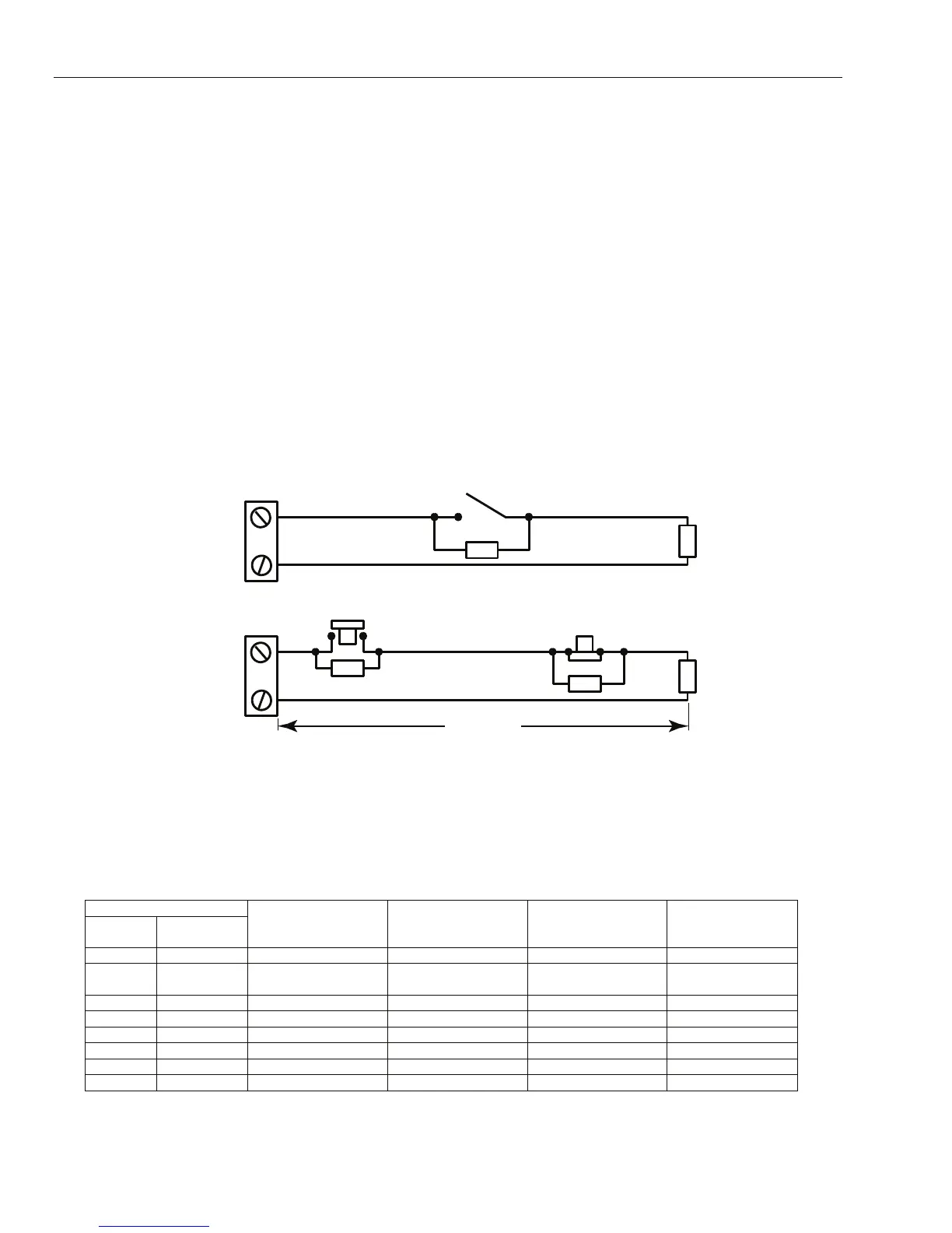
first push of the terminator. The wiring of the terminator and keyswitch zone type is shown in Figure 2-16:
Keyswitch
zone
Push-set
zone
1k to unset (disarm)
2k to set (arm)
1k
1%
Open - Closed
1k
1k
1k
1k
OR
Closed - Open
1%
1%
1%
1%
GX-016-V2
1640 ft (500 m)
Figure 2-16. Terminator and Keyswitch Zone Wiring
Outputs
The GX-Series control panel on-board outputs are detailed in the Table 2-9:
NOTE: The maximum current draw for the +12V AUX outputs is 1A, and for the switched AUX outputs is 400mA
(see TB1 – TB6 in Figure 2-4.) The total maximum load for output addresses 1001, 1003 – 1004 and
1011 – 1014 = 400 mA.
Output Address
Default
Line 0
Enable
Default Function Type Rating
Normal State
(with 3k3 pull-up)
1001 1001 Bells Transistorized 12V, see note above Positive
1002 1002 Strobe Single Pole Change
Over Relay (SPCO)
30V, 1A De-energized
1003 1003 PA Transistorized 12V, see note above Positive
1004 1004 Reset Transistorized 12V, see note above Positive
1011 0011 Set Transistorized 12V, see note above Positive
1012 0012 Intruder Transistorized 12V, see note above Positive
1013 0013 Confirm Transistorized 12V, see note above Positive
1014 0014 Reset Transistorized 12V, see note above Positive
Table 2-8. Outputs
 Loading...


