GX-Series Control Panel Installation and Setup Guide
3-2
control panel power supply or from a remote power supply if the distance causes a large voltage drop on the
cable.
Connect the RIO terminals as follows:
+12 V (either control panel, keypad or remote power supply);
–0 V or ground (either control panel, keypad or remote power supply);
A to the A terminal of the previous module (or control panel if RIO is the first on the line);
B to the B terminal of the previous module (or control panel if RIO is the first on the line).
NOTE: If the RIO is the last module on the line, connect a 680 Ω EOL resistor across the A and B terminals.
Configuring the RIO
The added RIO is configured into the system on exiting from engineer mode. If the message XX Mod Added
[<],[>] To View is displayed, the system has recognized that a new module is present. Press the A> or <B
keys to confirm that the RIO has been added. If this message is not displayed or the RIO is not on the list of
added modules, then the RIO is not communicating with the control panel or has been set to the same
address as the RIO already connected to the system. The flash rate of the red LED (LED1) on the RIO
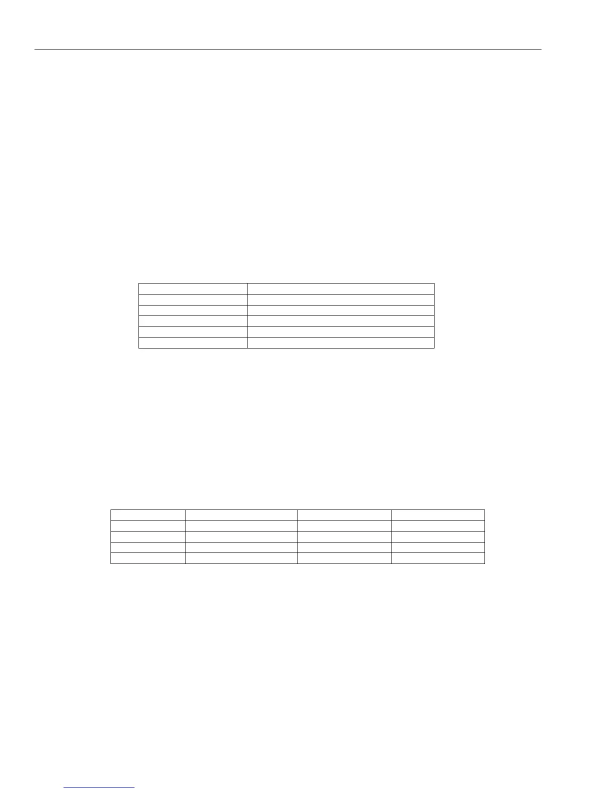
indicates the status of the communication with the control panel - refer to Table 3-3.
Flash Rate (seconds) Meaning
0.1 ON / 0.9 OFF Normal communications
OFF No DC supply
1.5 ON / 1.5 OFF RIO has not been configured into system
0.2 ON / 0.2 OFF RIO has lost communication with system
0.9 ON / 0.1 OFF Very poor communications
Table 3-3. RIO LED Flash Rates
RIO Zones
The GX-Series RIO has eight programmable zones. These default to INTRUDER. Each zone is Double
Balance monitored with a 1 k• resistor in series with the zone detector and a 1 k• (1%) resistor in parallel
across the detector switch. The change to 2 k• (1%) resistance registers the zone as open/alarm.
RIO Outputs
The RIO has four transistorized outputs. Each output is connected to +12 V via a 3.3k• pull-up resistor
(refer to Table 3-4). When an output is activated, the load is switched to the negative supply voltage (ground
or 0 V) of the RIO. The total current available from the RIO outputs 1 - 4 is 700 mA. The default functions
and pull-up resistors of each RIO output, when connected to a GX-Series are shown in Table 3-4.
Output No. Function Maxium Load Pull-up Resistor
1 Bells 400 mA R1
2 Strobe 100 mA R3
3 PA (Personal Attack) 100 mA R5
4 Reset 100 mA R7
Table 3-4. RIO Output Default Functions
Ethernet Module
NOTES: For UL installations use a DTK-MRJ45C5E Ethernet surge protector.
In UL 1076 compliant systems, the Ethernet module must be used as the primary means of
communication.
In UL installations, do not use an Ethernet card in wireless LAN or WAN configurations.
The Ethernet Module is an optional add-on to the GX-Series control panel. It is a highly intelligent and
compact module, combining alarm signaling, remote servicing and integrated facilities over Ethernet LAN
and/or WAN. The Ethernet Module connects to 10 Base T Ethernet networks both supporting UDP/IP and
TCP/IP protocols. The Ethernet module supports the following features:
 Loading...


