GX-Series Control Panel Installation and Setup Guide
2-5
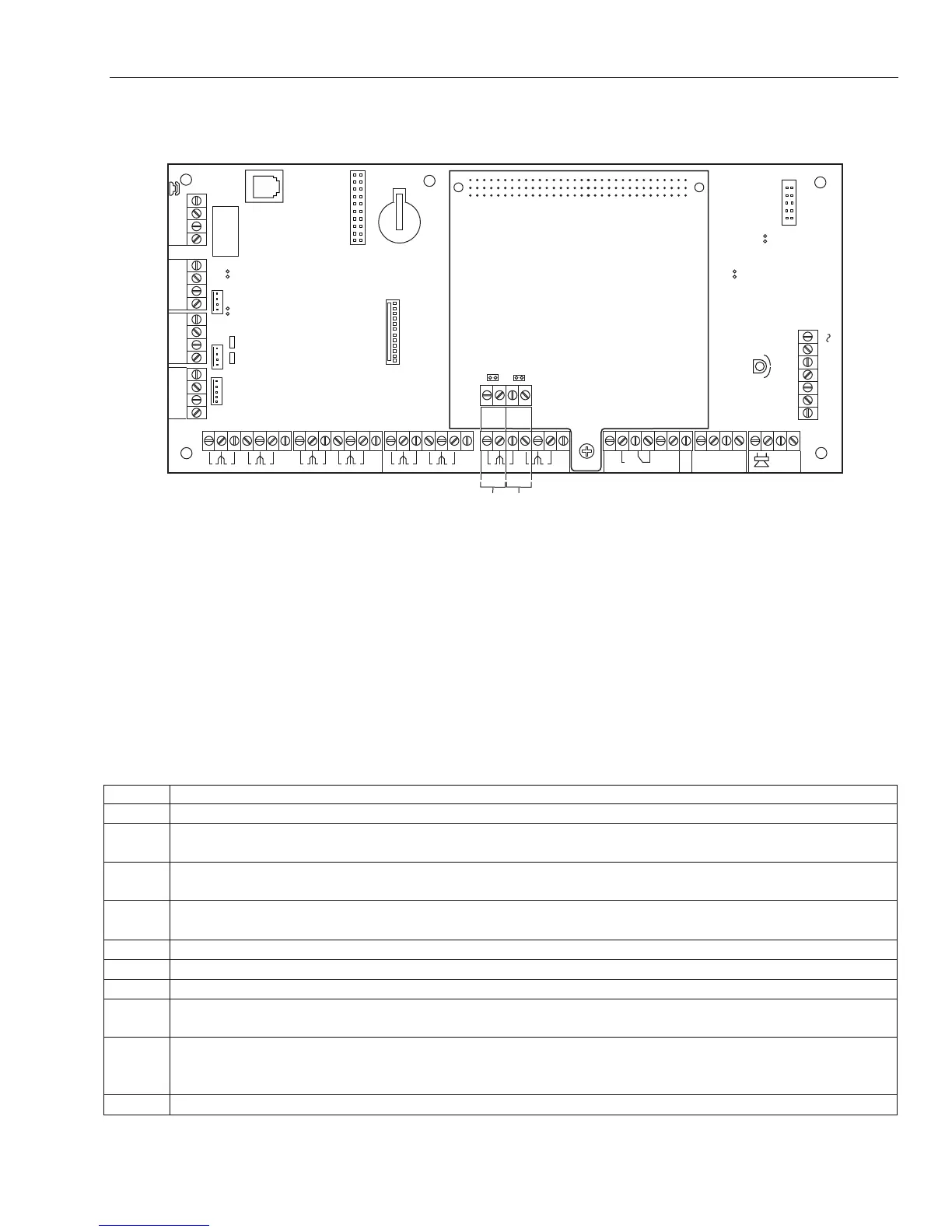
RS485 Expansion Module (GX-520 only)
The RS485 Expansion Module is attached to the GX-520 to give 2 extra RS485 (AB) lines.
LID
TAMP
+12V
+12V
+12V
+12V
1
2
3
4
2
AUX
TAMP
G
N
D
RX
TX
B2
A2
A1
B1
+12V
PHONE
LINE
A
B
AB
AC
RIO 0
13
RIO 1
GND
GND
+12V
CTS
RTS
+12V
4
14.5
+BAT
-BAT
11
22 33
44 55
66
77 88
N/O
C
N/C
ONON
1
2
0V
3
4
0V
RIO 0
5
6
0V
7
8
0V
1
2
0V
3
4
0V
RIO 1
5
6
0V
7
8
0V
SKT2
RS485
EXPANSION
MODULE
GX-005-V1
RS485
LINE 4
(NOTE 1)
RS485
LINE 3
(NOTE 1)
A4
A3
B3
B4
RS485 DATA BUS LINES MUST USE DAISY CHAIN
WIRING BETWEEN MODULES.
EACH END OF THE RS485 DATA BUS MUST BE
TERMINATED WITH A 680 OHM RESISTOR ACROSS
THE A&B WIRES. IF THE PANEL DOES NOT FORM
ONE END OF THE BUS, REMOVE THE LINK TO DISABLE
THE 680 OHM RESISTOR.
NOTE 1:
NOTE 2:
RS485 LINE 4 680 Ω TERMINATION (SEE NOTE 2).
RS485 LINE 3 680 Ω TERMINATION (SEE NOTE 2).
Figure 2-5. RS485 Expansion Module
Transformer Installation Instructions
Use the supplied 1451 Transformer. This transformer provides 18VAC/72VA secondary winding for
powering the control and has a manually resettable circuit breaker mounted inside a protective metal
enclosure. To connect the 1451 transformer to the control, perform the following steps (refer to Figure 2-6):
Notes: 1. Make sure the circuit breaker that controls the circuit providing power to the control unit is in the OFF position.
2. The 120VAC circuit that the transformer is connected to should be dedicated to powering the control unit, should
provide power continuously for 24 hours, and should not be controlled by a wall switch.
3. All circuits are power limited except the output of the 1451 transformer and the battery.
Step Action
1. Remove the front cover.
2. Mount the 1451 transformer enclosure to the wall near the control panel. The enclosure has four
mounting holes on its back surface for this purpose.
3. Identify the circuit breaker or fuse controlling the circuit furnishing power to the control unit.
Make sure it is in the OFF position.
4.
Run 120VAC wiring from the circuit breaker or fuse to the enclosure in conduit. A dedicated
circuit must be used.
5. Use wire nuts to splice the 120VAC wires to the transformer’s white and black primary leads.
6. Connect the earth ground post on the back of the enclosure to a good earth ground.
7. Run 16AWG wire in conduit from the enclosure to the control panel.
8. Route the wire through a knockout on the left-hand side of the control unit's enclosure. Tie-wrap it
to a tie wrap loop near the knockout to separate it from other power-limited wiring.
9. Use wire nuts to splice the transformer blue 18VAC secondary leads to the 16AWG wire. Connect
the 16AWG wire at the control panel to the AC terminals on the control panel. See Figure 2-4 for
exact location of the AC connections on the PCB.
10. Replace the front cover of the enclosure and fasten it with the screws supplied.
 Loading...


