GX-Series Control Panel Installation and Setup Guide
5-4
LED Output
LED output 3 is used to drive a reader LED. It is open collector and can switch up to 100 mA. LED outputs
1 and 2 are not used. The LED gives a visible indication on the reader of car read and access granted.
Relay Output
This is a relay output which is activated upon any valid card read or RTE button operation in order to
temporarily unlock the door. The relay can switch up to 1 A @ 30VAC.
Installation and Mounting
The DCM can be supplied installed in a standard plastic RIO box or within a Power RIO box.
Mounting the RIO Box
1. If necessary, remove the DCM PCB from the box to allow access to the screw holes.
2. Fix the base to the mounting surface, using the screw holes provided.
3. All cables must be brought into the enclosure base via the cable entry points. There are six cable entry
holes for the entry of alarm cables.
4. Attach the RIO box lid with the four thread forming screws provided.
Wiring the Reader to the DCM
The wires from the Reader are connected to the Wiegand Reader Inputs (see Figure 5-1). Refer to separate
Reader instructions for method of wiring the Reader to the DCM.
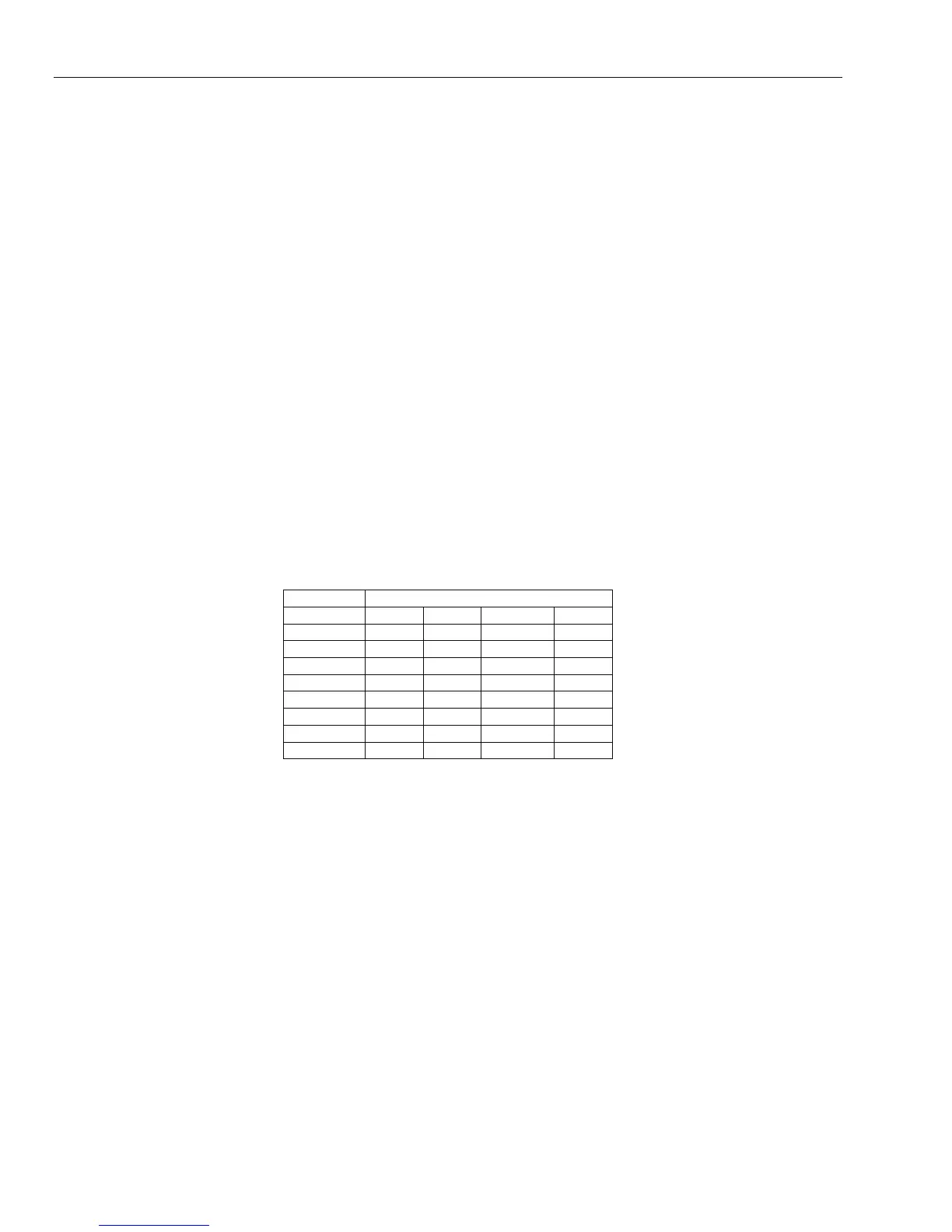
Addressing with DIP Switches
The DCM must be given a unique address before it is connected to a power supply. The DCM can be
addressed with the DIP switches. The addressing works in a binary mode. The following table shows each
DIP switch with related address number. Switches 4 to 8 must be left in the off position.
Switch
Address 1 2 3 4-8
0 OFF OFF OFF OFF
1 ON OFF OFF OFF
2 OFF ON OFF OFF
3 ON ON OFF OFF
4 OFF OFF ON OFF
5 ON OFF ON OFF
6 OFF ON ON OFF
7 ON ON ON OFF
Table 5-1. DIP Switch Addressing
Connecting the DCM to GX-Series System
The DCM must be wired to the GX-Series RS485 (AB) line in parallel (daisy-chain configuration). The DCM
requires 12VDC. See Figure 5-1 for a diagram of the connections.
NOTE: If the DCM is the last module on the line, connect a 680 Ω EOL resistor across the A and B terminals.
Configuring the DCM
The added DCM is configured into the system on power up of the control panel or when exiting from
engineer mode. The flash rate of the green comms LED (LED1) on the DCM indicates the status of the
communication with the control panel. A short flash once per second indicates good communications. LED 2
when lit indicates that there is power to the DCM.
 Loading...


