GX-Series Control Panel Installation and Setup Guide
2-1
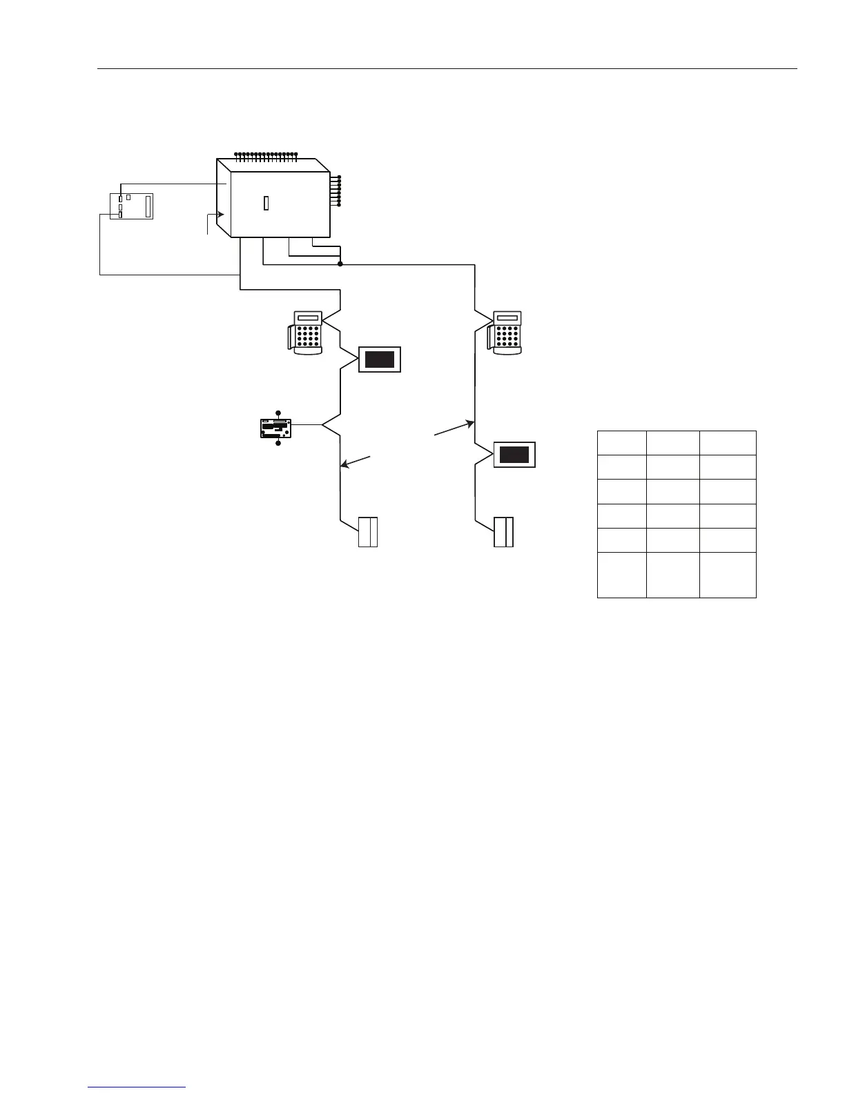
SECTION 2: SYSTEM ARCHITECTURE
16 zones on board
GX Series
Line
Line
12
NOTE:
The Ethernet module can only be
connected to line 1.
If an Ethernet module is attached,
keypad address B cannot be
connected to line 1 (address B is
shown as 15 on the system).
CABLE RUN 1 KM (MAX)
Keypads
Mk 7
*
8 outputs
on board
plus 6 outputs
on trigger header
on board
telecom
area
Certain keypad and
max addresses can
be replaced by a
combined keyprox unit.
*
NOTE:
Valid addresses for the
keyprox are:
Line 1 (0, 1 & 2).
Line 2 (0, 1, 2, & 3 ).
This sets the address for both
the keypad and card reader
parts of the keyprox.
*
K
eypad
Mk 7
*
PSTN (comm 1)
Audio Interface
Module (1)
‡
RS485 line
RS232
Serial Port
(comm 6)
8 zones
4 outputs
RIO
C072
Twisted Pair
Screened Cable
Touch
Center
CP041
DCM
C080/81
DCM
C080/81
Touch
Center
CP041
Line Line
3
4
Lines 2, 3 and 4 have
the same configuration
Trigger
Header
GX-001-V4
‡ Not Evaluated by UL.
GX-48 GX-520
Lines
1 4
Keypa
ds
8 8 per line
Touch
Center
1 1 per line
DCM's
4 8 per line
RIO's
4
15 (line
1)
6 (lines
2, 3, 4)
Figure 2-1. GX-Series System Configuration
 Loading...


