GX-Series Control Panel Installation and Setup Guide
3-1
SECTION 3: PERIPHERALS
General
The following peripherals can be connected to the GX-Series panel:
All bus lines: Mk7 Keypad; TouchCenter; Door Control Module (DCM);
Remote Input Output module (RIO).
Bus line 1 only: Ethernet.
Wiring
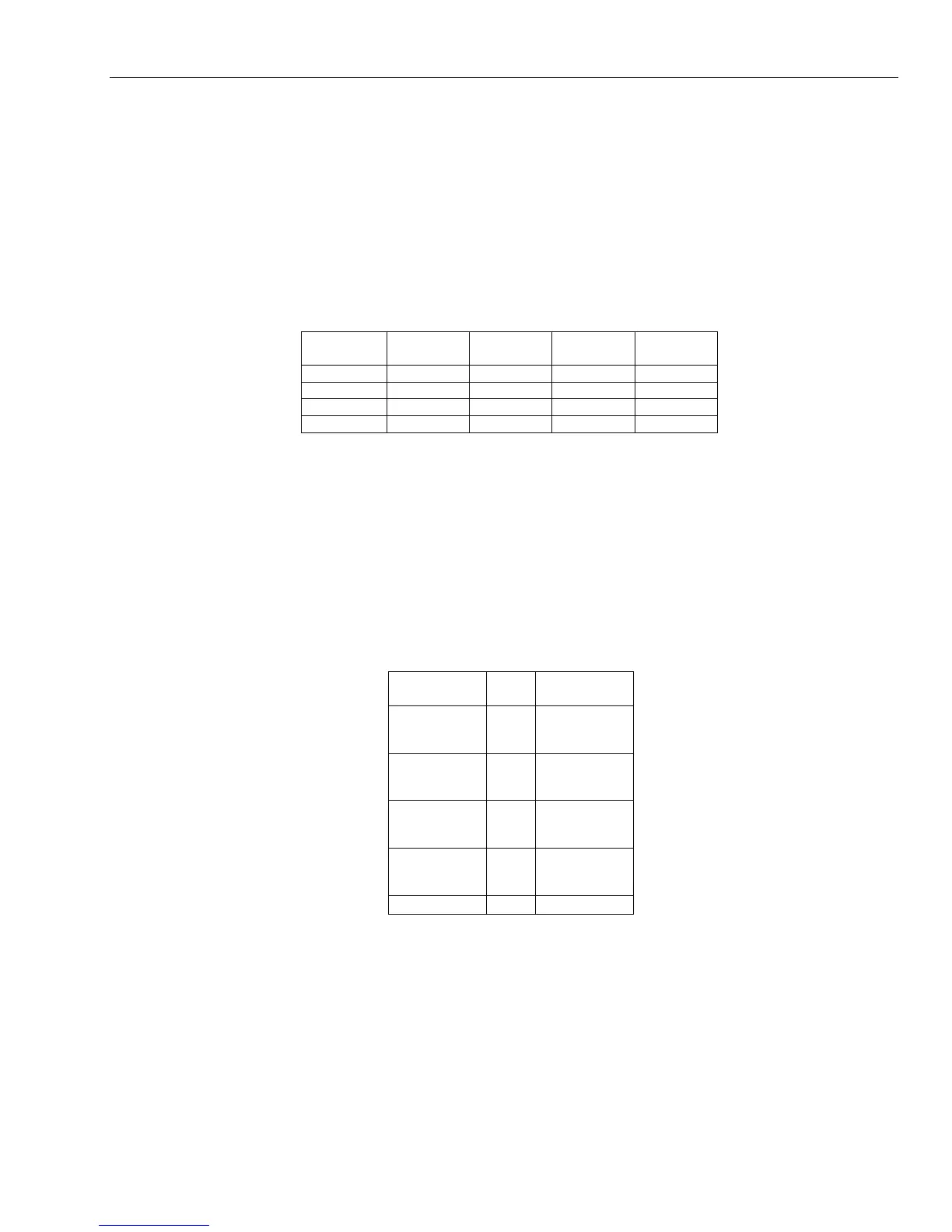
The following table shows the wiring between the GX-Series panel and the different peripherals.
Panel Keypad
Touch
Center
RIO &
DCM
Audio
Interface
+12V + + Vin +12V
GND - - - GND
A A G A A
B B Y B B
Table 3-1. Peripheral Wiring to GX-Series Panel
NOTE: Do not connect +12V terminals between panels and
remote power supplies.
Configuring
New peripherals will be configured onto the system at system power up or on leaving programming mode.
Changes to peripheral addresses will only take effect when the peripheral is re-powered.
Addressing
The address on most peripherals is set by either jumpers or a rotary switch. These must be set before the
system is powered up. Table 3-2 shows the available peripheral addresses.
Peripheral Line
VALID
ADDRESSES
Mk7 Keypad
1
2
3-4
0-2, B-F
0-6, F
0-6, F
TouchCenter
1
1
2
3-4
0-2
0-3
0-3
RIO 1
2
3-4
2
2
-9 & A-F
0-9 & A-F
0-9 & A-F
DCM 1
2
3-4
0-7
0-7
0-7
Ethernet 1 (B)
Table 3-2. GX-Series Peripheral Addresses
NOTES: 1. A single TouchCenter can be installed on each bus line.
2. If RIO 2 on-board is set to line 0 (Dip SW 8) then the first external RIO can use address
1 to give an extra 8 zones where needed.
Connecting the RIO
The RIO can only be connected to the system while engineer mode is accessed. The RS485 (AB) line of the
GX-Series RIO must be wired in parallel (daisy-chain configuration) with the RS485 (AB) line of any
keypads connected to the system. The RIO requires 12 VDC and 40 mA. This can be supplied from the
 Loading...


