GX-Series Control Panel Installation and Setup Guide
2-7
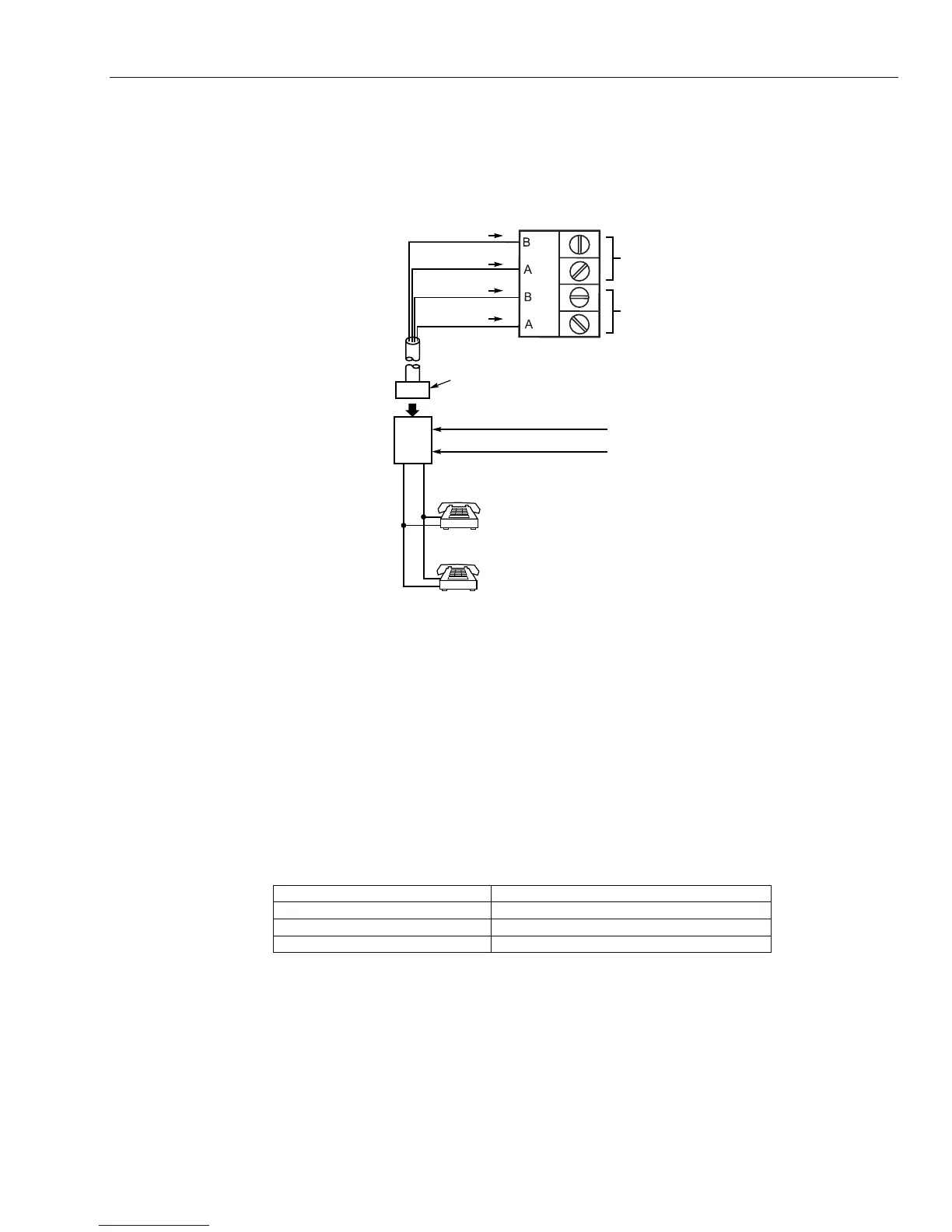
Connecting the GX-Series to the PSTN
Connect incoming phone line and handset wiring to the main terminal block (via an RJ31X jack) as shown in
Figure 2-7. Wire colors represent the colors of the cable to the RJ31X jack. MX-8000 or 685 dialers are for
supplementary central station use. Computer is the primary central station.
BROWN (TIP)
GREY (RING)
GREEN (TIP)
RED (RING)
INCOMING TELECOM LINE
PHONE
TIP
RING
RJ31X
JACK
PLUG
DIRECT
CONNECT
CORD
TIP
RING
PREMISES
PHONES
LINE
GX-007-V0
TERMINALS
ON CONTROL
LINE
PHONE
Figure 2-7. Connecting the GX-Series to the PSTN (Incoming Telephone Line)
Connect the on-board Telecom Module to the PSTN as shown in the diagram.
Notes: 1. Terminals 1 and 2 must be hard-wired to LINE A (Tip) and B (Ring) terminals on the GX-Series PCB.
The connection is polarity independent.
2. It is strongly recommended that the GX-Series panel is the only device on the line.
3. Audio module not evaluated by UL.
Note: If a Digital Subscriber Line (DSL) is used, a suitable filter must be used for the phone line.
Line Monitoring
Under normal idle state conditions, the on-board Telecom Module monitors the PSTN line.
PSTN LED (Green): If a telephone line fail is detected by the Audio Interface this LED will flash repeatedly
at: 200ms ON/200ms OFF. When the telephone line fail condition clears this flashing LED will then go OFF.
LED Flash Rate (seconds) Meaning
OFF No DC supply
ON - 01s, OFF - 0.9s Normal Communication
09 ON / 0.1 OFF Very poor communications
Table 2-2. Communications Status
Stand-By Battery
The GX-Series control panels can accommodate up to 2 x 17 Ah batteries. Ensure that the battery connector
leads on the control panel Powers Supply Unit (PSU) are connected to the correct terminals on the battery.
CAUTION: There is a risk of explosion if the battery is replaced by an incorrect type. Dispose of used batteries
according to the instructions.
 Loading...


