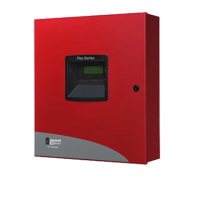
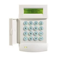
GX-Series Control Panel Installation and Setup Guide
2-8
Control Panel Battery
-BAT -ve terminal
+BAT +ve terminal
Table 2-3. Battery/Control Panel connections
NOTES: 12V 7AH battery capacity is required for emergency standby for at least 4 hours.
Two 12V 7AH batteries are required for standby power in UL installations.
Accommodation of 2 x 17 Ah batteries not evaluated by UL.
When connecting batteries in parallel:
- Battery normally need not be replaced for at least 3 years.
- Use batteries from the same manufacturer and with the same voltage and capacity rating.
- Use batteries with approximately the same age and state of charge.
- Use cables provided, and observe polarity!
- It is recommended that all batteries be replaced at the same time, even if only one battery has
become weak.
Battery Start-up
The system can be powered up via the Battery Start-up jumper if there is no AC power. To do this, short
out the Battery Start-up jumper for the duration of the configuration process only. Never leave the Battery
Start-up connected or else deep discharge of the Stand-by Battery will occur.
Power Monitoring Characteristics: Low battery level: 11.2V
Deep discharge protection: 10.2V
Overvoltage protection: 14.7V
Internally the PSU is split in two in order to ensure sufficient current is always available for stand-by
battery recharge. The PSU capacity is broken down as follows:
• Battery: 1.25A
• Control PCB: 0.25A
• AUX +12V: 1.00A
The PSU is available for zones/outputs and peripherals.
Memory
The GX-Series control panel has a built-in memory chip with its own battery backup on the main PCB. This
allows the panel to retain the system configuration, programming details and the event log for up to a year
when both the mains power and standby battery have been disconnected. The memory backup battery must
be kept in place to retain the memory during a mains failure. Re-apply power, this is known as a warm
start.
To completely erase the system memory and return to the default settings, place a piece of thin card between
the retaining clip and the memory backup battery then remove all power to the PCB for one minute. Re-
apply power and remove the card. This is known as a cold start.
The memory backup battery should be replaced every 5 years, by a trained installer only.
Memory backup battery replacement:
1. Remove memory backup battery with a small flat head screwdriver.
2. Replace with a good battery.
3. Reconnect mains supply.
4. Reconnect 12V battery.
CAUTION: There is a risk of explosion if the battery is replaced by an incorrect type. Dispose of used batteries
according to the instructions.
Do not overstress the retaining clip when removing and installing the backup battery. The clip must
maintain a firm pressure on the backup battery at all times.
Replacement Batteries: Panasonic CR2025; or Varta Batteries CR2025.

 Loading...


