GX-Series Control Panel Installation and Setup Guide
2-16
Output Address Default function Current (mA)
0001 Fire 100
0002 Panic 100
0003 Intruder 100
0004 Set (Arm) 100
0005 Omit (Bypass) 100
0006 Confirm 100
Table 2-9. Trigger Output functions
The function of the trigger outputs can be programmed in menu option 53 = Program Outputs.
NOTE: Not evaluated by UL.
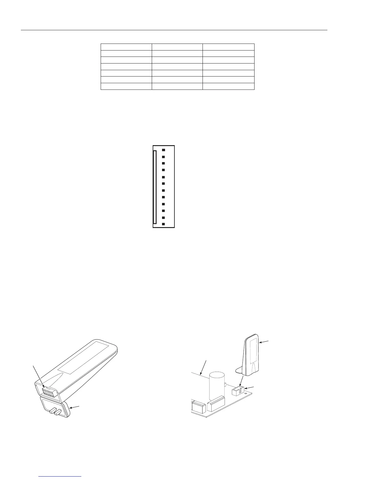
Supply
A 100 mA, 12V output is also provided.
Not Used
Not Used
GND
+12V
Trig 1
Trig 2
Trig 3
Trig 4
Trig 5
Trig 6
Not Used
Not Used
GX-019-V0
Figure 2-19 Trigger Header
SPI Header
The SPI (Serial Peripheral Interface) key is an engineering peripheral used for copy/overwriting
programming data and carrying out software upgrades.
Fitting the SPI Key
The SPI key is inserted directly on to the GX-Series control panel.
CAUTION: Always power down the panel BEFORE removing or connecting the SPI key. Failure to do so may
result in damage to the SPI key. Never “hot-plug” the SPI key.
The SPI Key has a 10-way connector. These locate on to the 10 pins of the SPI Program Header (see Figures
below).
NOTE: The SPI Key should only be inserted in the direction shown in Figure 2-19.
HINGED
CAP
GX-020-V0
10-WAY
CONNECTOR
Figure 2-20. SPI Key
GX-021-V1
CONTROL PANEL
(PARTIAL VIEW)
SPI KEY
INSERTED
HERE
SPI PROGRAM
HEADER
Figure 2-21. Location of SPI Key on Program Header
 Loading...


