GX-Series Control Panel Installation and Setup Guide
2-6
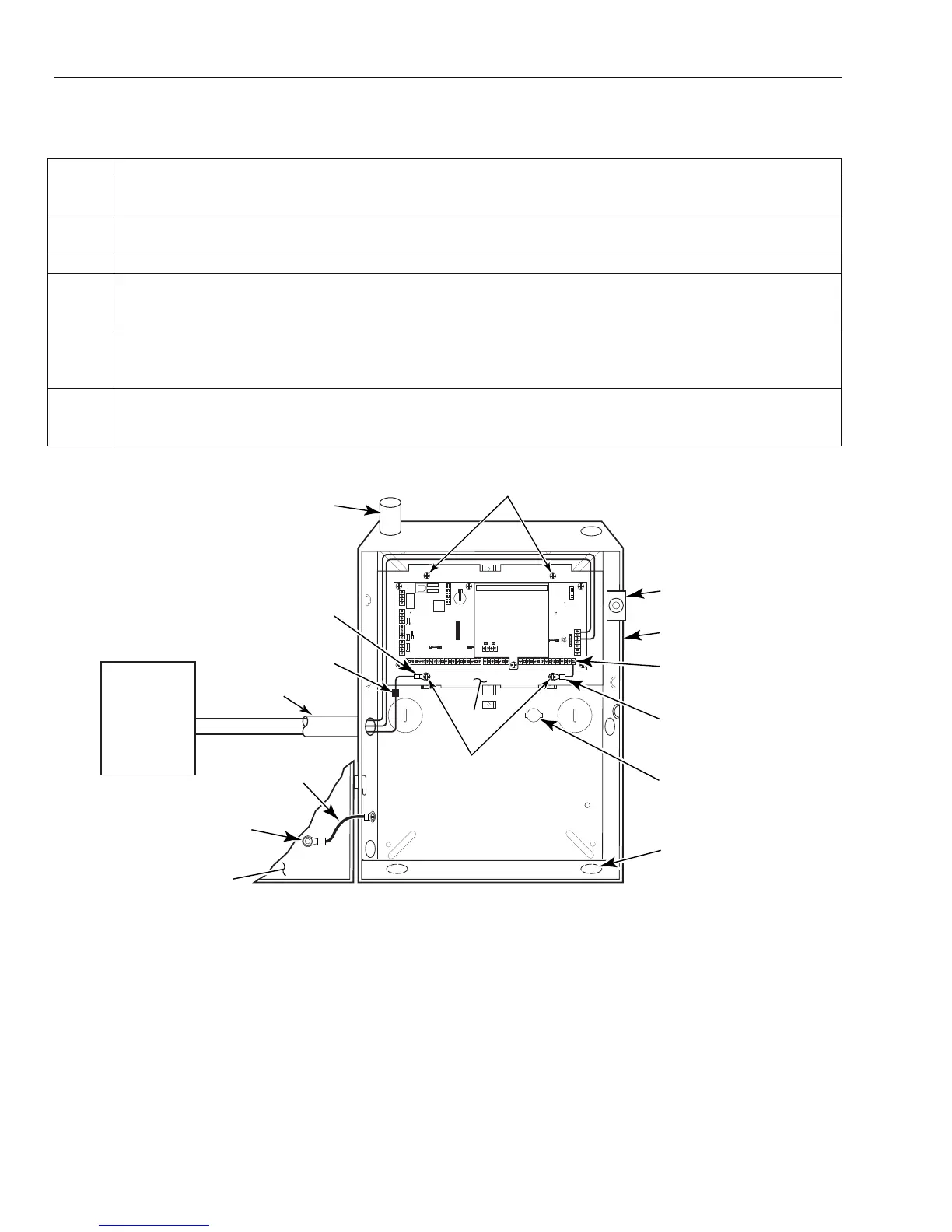
Connecting the Control Unit to Earth Ground
To connect the system to earth ground, perform the following steps:
Step Action
1. Connect the earth ground post inside the transformer enclosure to a good earth ground (use
grounding methods specified in the National Electric Code).
2. Use a green nut (supplied) to secure the green ground wire to the ground post. The earth ground
wire should be the only wire under this nut.
3. Run 16AWG wire from this post through conduit into the control unit enclosure.
4. Take a ring terminal harness and cut it in half. Connect the wire end of the ring terminal harness
with a wire nut to the 16AWG wire from the conduit and take the ring terminal end and place it
under the mounting plate screw. See Figure 2-6.
5. Take the other end of the ring terminal harness and insert the bare wire end into the ground
(GND) terminal block on the main PCB and place the ring end under the mounting plate screw.
See Figure 2-6.
6. To ground the cabinet door to the cabinet take the ring terminal harness and place both ends on
the mounting post on the door and cabinet and secure it with a washer and green nut. See
Figure 2-6.
WIRES MUST
BE RUN IN
CONDUIT
RUN BELL WIRES
IN CONDUIT
DOOR TAMPER
SWITCH LOCATION
1/2" RING
TERMINAL
HARNESS
1/2" RING
TERMINAL
HARNESS
REAR TAMPER
SWITCH LOCATION
CABINET
PLATE MOUNTING
SCREWS (2)
PLATE MOUNTING
SCREWS (2)
GX-103-V1
F1
11
2233
4455
66
7788
N/O
C
N/C
ONO
N
PC
BOARD
PLATE
TRANSFORMER
GND WIRE (GRN)
CABINET DOOR
NUT (GRN)
AND LOCKWASHER
RUN ALL REMAINING
WIRE THROUGH HERE
WIRE
NUT
GND
Figure 2-6. Installing the Control
Power Requirements
The GX-Series uses 1451 power supply as the primary power source. Because the system power is
distributed over the RS-485 buses, it is important to keep the voltage drops along the buses to a minimum.
Good installation practices will go a long way toward minimizing both the effect of the voltage drops and the
need for adding an external power unit.
Where additional power is needed, an Electronic Security Devices (ESD) SPS-6E power supply can be
introduced at sections of the bus. The power supply will provide power for its associated device and for
additional sections of the RS-485 bus, as well.
Note: Keep power
limited and non-power
limited wires a
minimum of ¼” apart.
 Loading...


