GX-Series Control Panel Installation and Setup Guide
4-1
SECTION 4: KEYPADS
Two types of keypad can be installed on the GX-Series: The Mk7 Keypad and the Touch Center keypad. Both
types of keypad are described in this section.
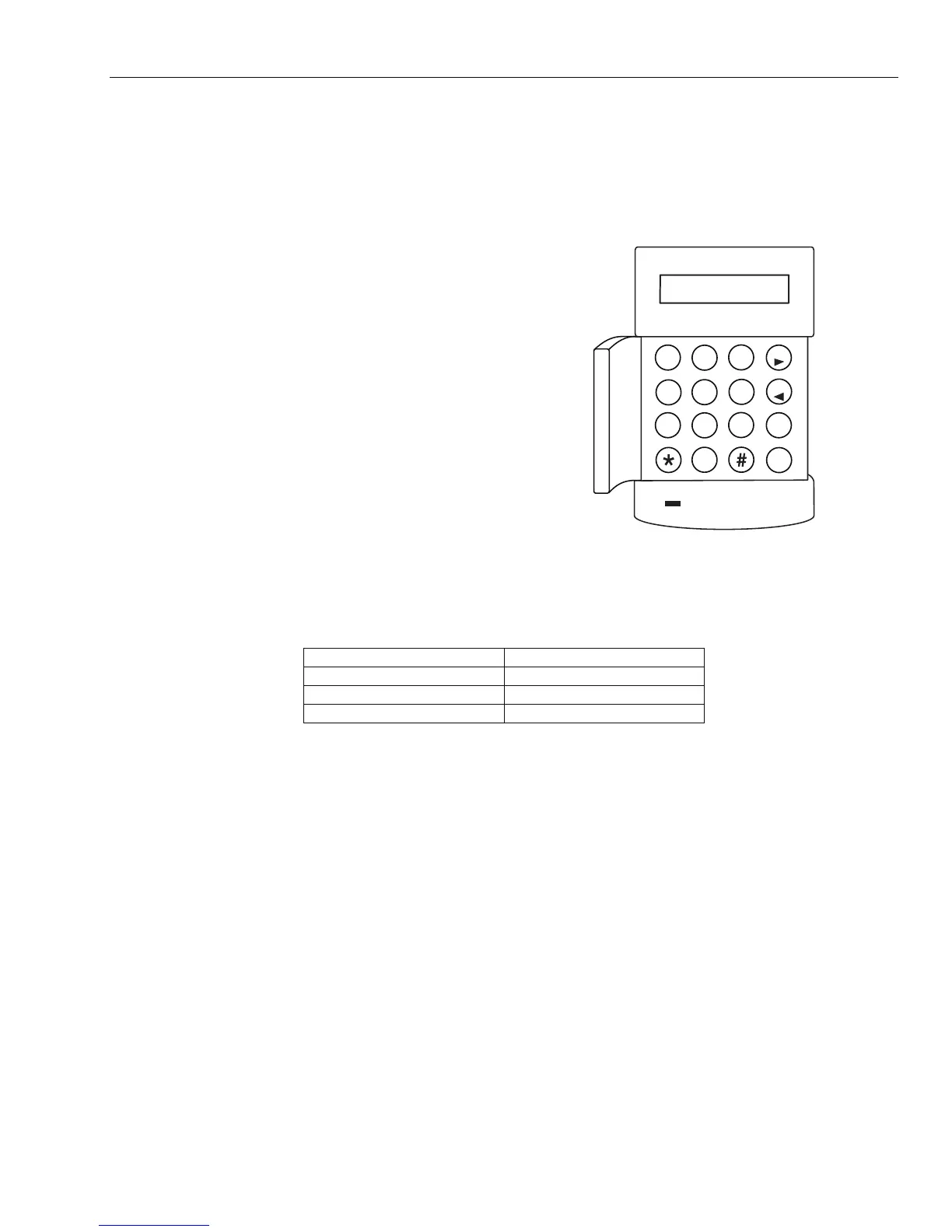
The GX-Series Mk7 Keypad
General
The GX-Series Mk7 keypad has the following
features:
• a 2 x 16 alphanumeric character backlit
display
• 16 backlit push buttons as shown in
Figure 4-1
• internal horn
• power indicator LED
• multi-function LED
• Lid tamper
• Off-wall tamper
• Address switch
• RS485 serial connector
GX XXX V6.00
08:58 TUE 22 NOV
1
2
3
A
4
5
6
B
7
8
9
ent
0
esc
GX-031-V1
Figure 4-1. GX-Series Mk7 Keypad
Power Consumption
The GX-Series Mk7 keypad requires a 12 VDC supply – from the control panel or a remote power supply.
The current consumption of the keypad is:
Mode Current Draw
Nominal (backlight OFF) 35 mA
Backlight ON 70 mA
Maximum Alarm Current 90 mA
Table 4-1. Keypad Current draw
Wiring the Keypad
A 16-way rotary address switch is used to address GX-Series LCD keypads. The address switch assigns a
hexadecimal address value to the keypad.
NOTE: Any change to the keypad address must be made when the power is disconnected from the keypad
Addressing
Addresses are set by means of a rotary switch on the PCB. Each keypad must be assigned a unique address
for its line. It is possible to add additional keypads at any unused comms module addresses (B, C, D and E)
as detailed below. These must be standard keypads. An engineer keypad can also be used at address F.
NOTE: On Line 1, keypad addresses B, C, D and E are not available if the Ethernet, ISDN, RS232 or Telecom
modules respectively are installed.
Keypad Installation Procedure
1. To attach the keypad to the wall, the back plate must first be removed from the front plate. To do this,
insert a suitable tool into both openings at the bottom of the keypad and turn the tool gently.
CAUTION: When the keypad is separated, make sure that the anti-static precautions are taken with the keypad
PCB to avoid damage from ESD (electro static discharge).
 Loading...


