GX-Series Control Panel Installation and Setup Guide
4-2
Connections to the terminals are:
Connector
Terminals
GX-Series
Keypads
A
A line to panel
B
B line to panel
+
12 VDC input
–
0 V
Table 4-2. Keypad Terminal Connections
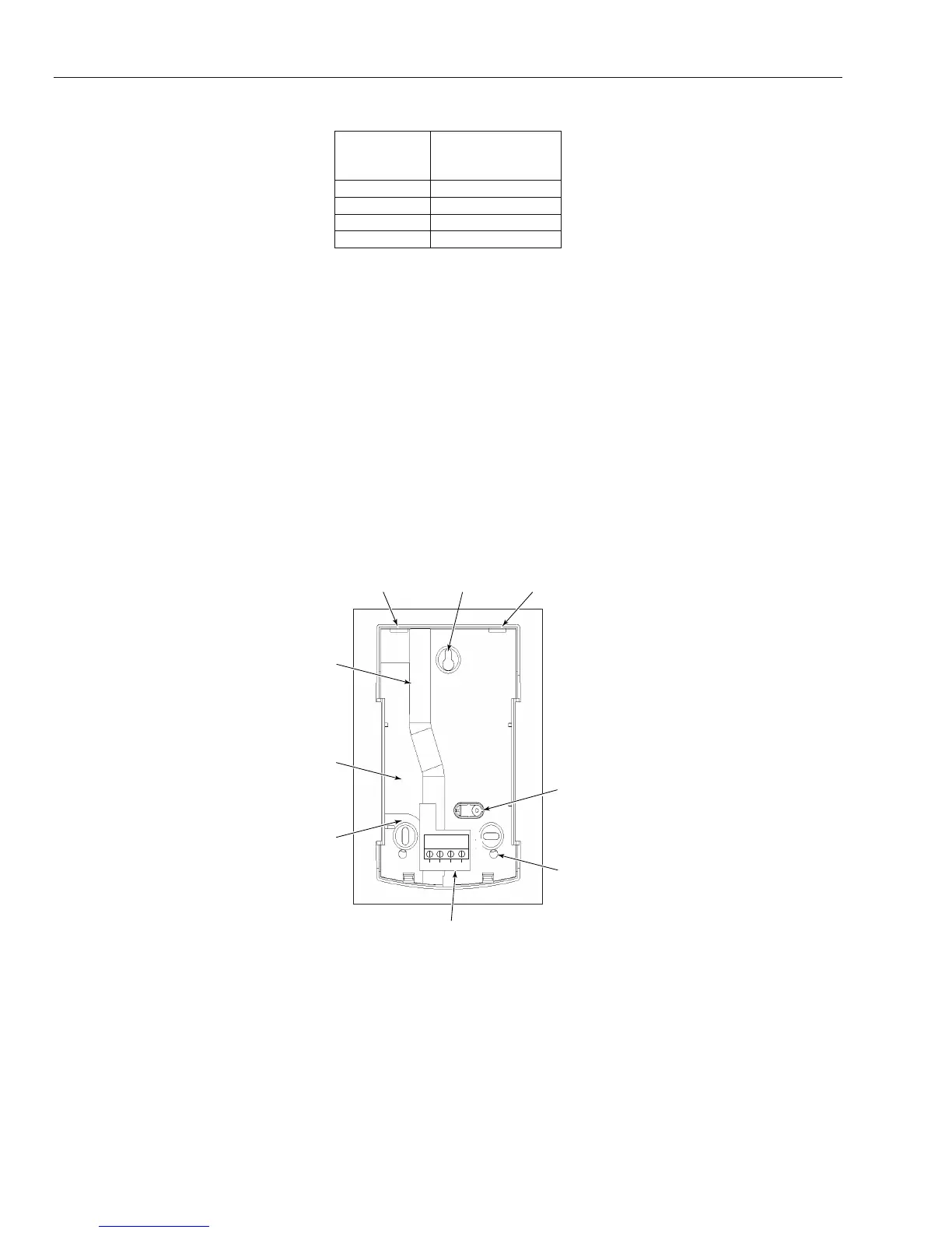
2. Use the backplate as a template, and mark the locations for the three attachment screws in the required
position.
3. If it is a new installation, use the keyhole slot at the top of the backplate and the two elongated holes at
the bottom.
4. If you are using a wall-run cable for the keypad (A, B, +12V, 0V) position the cable behind the back plate in
the cable channels provided. The cable can be run in from either the top or the bottom of the back plate. Use
a sharp tool to remove the plastic from the top or the bottom of the cable guides on the back plate skirting.
CAUTION: Use of any screws other than No. 6 pan-head can damage the keypad moldings.
5. Make sure that the keypad wiring is fed through the large opening on the keypad backplate, then
position the keypad base on the wall and attach it securely with the three No. 6 pan-head screws.
6. If an off the wall tamper is required, using a No. 6 pan-head screw, secure the breakaway wall tamper,
indicated in Figure 4-2, to the wall. Make sure that the tamper knockout is still connected to the
backplate molding.
7. Connect the A, B and power wires to the correct terminals of the removable, four-way connector block.
B
A
+
-
GX-032-V1
KEYHOLE SLOT
ELONGATED
HOLE
BREAKAWAY
WALL
TAMPER
4-WAY
CONNECTOR
KNOCKOUT
HOLE
CABLE
STOWAGE
AREA
APERTURE
APERTURE
CABLE
CHANNEL
Figure 4-2. GX-Series Mk7 Keypad Backplate Installation
8. Make sure that the power is disconnected then set the keypad to the required address using the 16 way
rotary switch on the PCB.
9. To re-assemble the keypad, connect the four-way connector block onto the pins on the keypad PCB.
Attach the keypad front plate to the back plate by inserting the two clips on the top of the keypad front
plate into the two apertures at the top of the keypad back plate, then gently push the bottom of the
keypad front plate into the back plate until it snaps securely into place. Ensure the front and back
sections of the keypad are securely fixed at all points of the keypad perimeter.
 Loading...


