GX-Series Control Panel Installation and Setup Guide
2-3
WIRES MUST BE
RUN IN CONDUIT
RUN BELL WIRES
IN CONDUIT
TAMPER
SWITCH
LOCATION
TAMPER
SWITCH
LOCATION
CABINET
MOUNTING
SCREWS
(3)
MOUNTING
SCREWS
(3)
GX-102-V1
PLUG THESE
KNOCKOUTS
PLUG THIS
KNOCKOUT
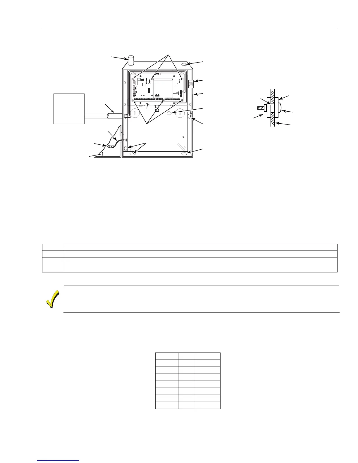
TO PLUG AN UNUSED KNOCKOUT OPENING,
REMOVE KNOCKOUT AND INSTALL A PAIR OF
DISC PLUGS AND A CARRIAGE BOLT AS SHOWN.
KNOCKOUT
OPENING
HEX NUT AND
WASHER
DISC PLUGS
(DIMPLES IN DISC
PLUG SHOULD
REGISTER INSIDE
KNOCKOUT OPENING)
CARRIAGE BOLT
CABINET SIDE WALL
(OUTSIDE)
F1
11
22 33
44 55
66
77 88
N/O
C
N/C
ONON
A4
A3
B3
B4
PC
BOARD
PLATE
TRANSFORMER
GND WIRE (GRN)
CABINET DOOR
PLUG THIS
KNOCKOUT
NUT (GRN)
AND LOCKWASHER
RUN ALL REMAINING
WIRE THROUGH HERE
Figure 2-3. Cabinet Attack Resistance Considerations
Mercantile Safe and Vault Listing Guidelines
• Follow the guidelines given above for Mercantile Premises listing.
• For safe and vault installations, a shock sensor (not supplied) that is listed for protection of sheet metal
enclosures, as well as an additional tamper switch, must be installed on the cabinet backbox to protect
the cabinet from being removed from the wall. These devices must also be wired to the cover tamper on
the PCB. See Figure 2-4 for the location of the PCB terminal block.
Installing the PCB in the Control
To install the circuit board in the cabinet, perform the following steps:
Step Action
1. Confirm the Mounting Plate is installed securely in the cabinet.
2. Place the board flat and secure to the mounting plate with the six accompanying screws. (See
Figure 2-3)
NOTE: Make sure that the mounting screws are tight.
Use shielded wire or keep wiring away from the microprocessor (center) section of the PC board. Use the
mounting plate brackets on the left and right sidewalls of the cabinet for anchoring field wiring using tie
wraps (Figure 2-3). These steps are important to minimize the risk of panel RF interference with television
reception.
The 7 transistorized outputs on the GX-Series can be configured to open collectors by setting the dip switch
SW3 to the OFF position. Table 2-1 shows which outputs are controlled by which switches.
Note: Output 2 on RIO 0 (relay output) is not affected. This is a form C relay that can switch up to 1 amp at
24 volts DC.
(SW3) RIO Output
1 0 1
2 0 3
3 0 4
4 1 1
5 1 2
6 1 3
7 1 4
Table 2-1. SW3 Transistorized Output Control
 Loading...


