GX-Series Control Panel Installation and Setup Guide
5-3
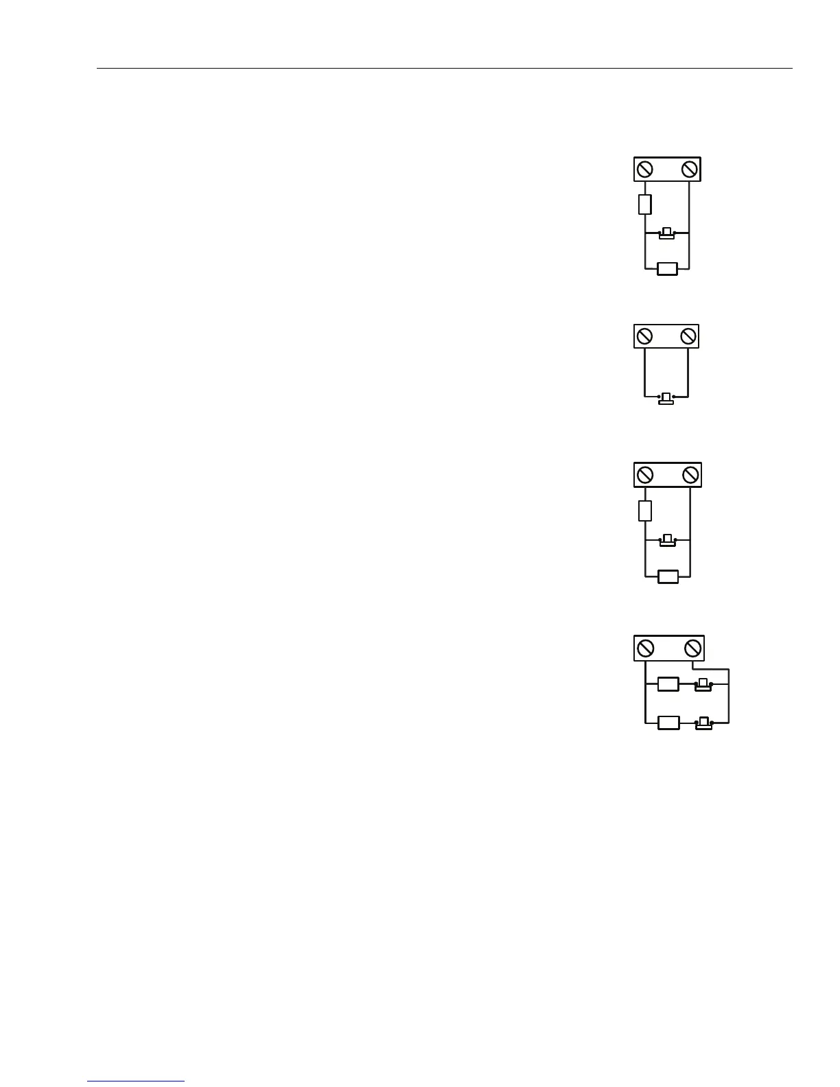
Inputs
The DCM includes the following sensing inputs:
Door Contact (DC)
This input is a normal alarm zone input that has the same functionality as a
normal security zone type. It uses normal 1k/2k double balanced zone wiring.
GX-041-V0
DC
0V
NORMALLY
CLOSED
DOOR
CONTACT
WIRING
1k
1k
Request To Exit Contact (EC)
This input is a normally open contact. When activated it will allow the door to
unlock for the programmed duration. Additionally, the door can be held unlocked
indefinitely by holding the EC closed. In this case, the relay activates only for the
programmed duration but the door propped alarm is held off. This can be
achieved, for example, by using a keyswitch wired in parallel with the normal EC
button.
GX-042-V0
EC
0V
NORMALLY
OPEN
REQUEST
TO EXIT
CONTACT
WIRING
Function Contact
This uses normal 1k/2k double balanced zone wiring. It has the function of
initiating a pre-programmed menu option following a valid card. The normal use
is to activate the arming (setting) procedure via the reader but any menu option
can be programmed.
GX-043-V0
FC
0V
NORMALLY
CLOSED
FUNCTION
CONTACT
WIRING
1k
1k
Tamper Inputs
The tamper circuits for both readers should be wired to the same tamper
terminals on the DCM. The two circuits are wired in parallel, each with its own
series resistor as follows:
The reader tamper is double-balanced.
• Reader 1 - 5.6k•
• Reader 2 - 12k•
GX-044-V1
NORMALLY
CLOSED
TAMPER
CONTACT
WIRING
TC
0V
5.6k
12k
Connecting a Wiegand Device
A standard Wiegand card reader or keypad can be connected to the DCM. The keypad can operate in 4-bit
and 8-bit burst mode.
Wiegand Reader Inputs
The wires from the Reader are connected to the Wiegand Reader Inputs (see Figure 5-1). Refer to separate
Reader instructions for method of wiring the Reader to the DCM.
Buzzer Output
This activates the buzzer on the reader to indicate card read, access granted and card rejected. The output is
open collector and can switch up to 100 mA.
 Loading...


