GX-Series Control Panel Installation and Setup Guide
5-2
Shield
U EXT
0V
D0/
CLK
D1/
DATA
LED
Red
LED
Ye l
LED
Grn
BUZ
BC
0V
EC
DC
0V
FC
NC
C
NO
Shield
U EXT
0V
D0/
CLK
D1/
DATA
LED
Red
LED
Ye l
LED
Grn
BUZ
BC
0V
EC
DC
0V
FC
NC
C
NO
RS485
BUS1/2
Shield
U in
0V
Data
0V
0V
A
B
12 v
input
Bus 1/2 not
supported
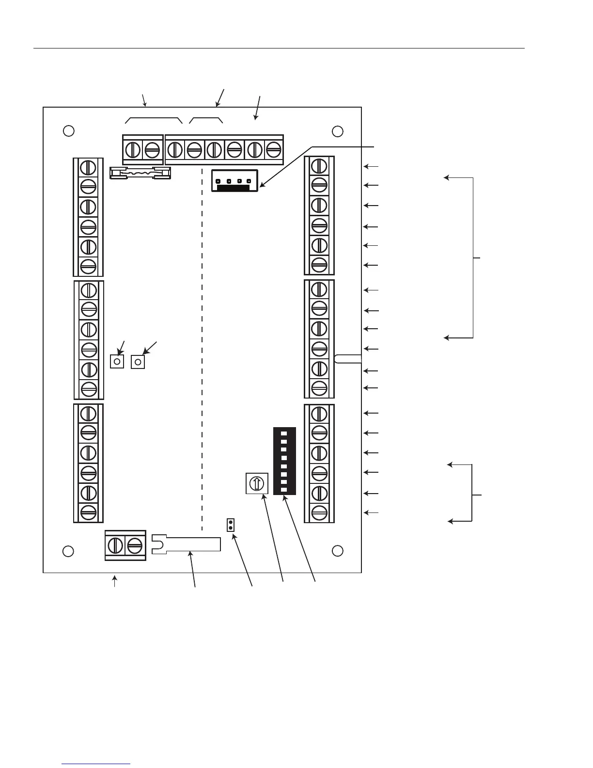
GX-Series
RS485 connect
Common pin for
connecting cable shield
12 volt output
0 volt connect
DO (Data Out)
DI (Data In)
LED 1
LED 2
LED 3
Buzzer output for reader
1
2 3
4 5
6
7 8
ON
Not Used
0 volt connect
RTE contact
Door contact input
0 volt connect
Function contact
(menu button)
Normally closed relay
Common pin relay
Normally open relay
TC 0V
Lid tamper
switch
Tamper
connect
Rotary
address
Switch
DIP Switches
Engineer Header
Wiegand
Reader
Inputs
Relay
outputs
form C
Reader 1
Reader 2
Door 1
Door 2
Jumper for
lid tamper
LED 2
(power)
LED 1
(comms)
GX-040-V1
Figure 5-1. Door Control Module PCB
NOTES: 1. If only one door is being connected, then always use the connections for Door 1 (Left Side) and terminate the
inputs with a 1K resistor.
2. When door readers are being connected for entry and exit to the same door, then connect the entry reader to
Door 1 and connect the exit reader to Door 2.
 Loading...


