GX-Series Control Panel Installation and Setup Guide
6-65
Option 53 – Program Outputs
This option is used by the engineer to modify the programming of the outputs on the system. The option also
allows the attributes of the outputs to be changed. The programmable options are:
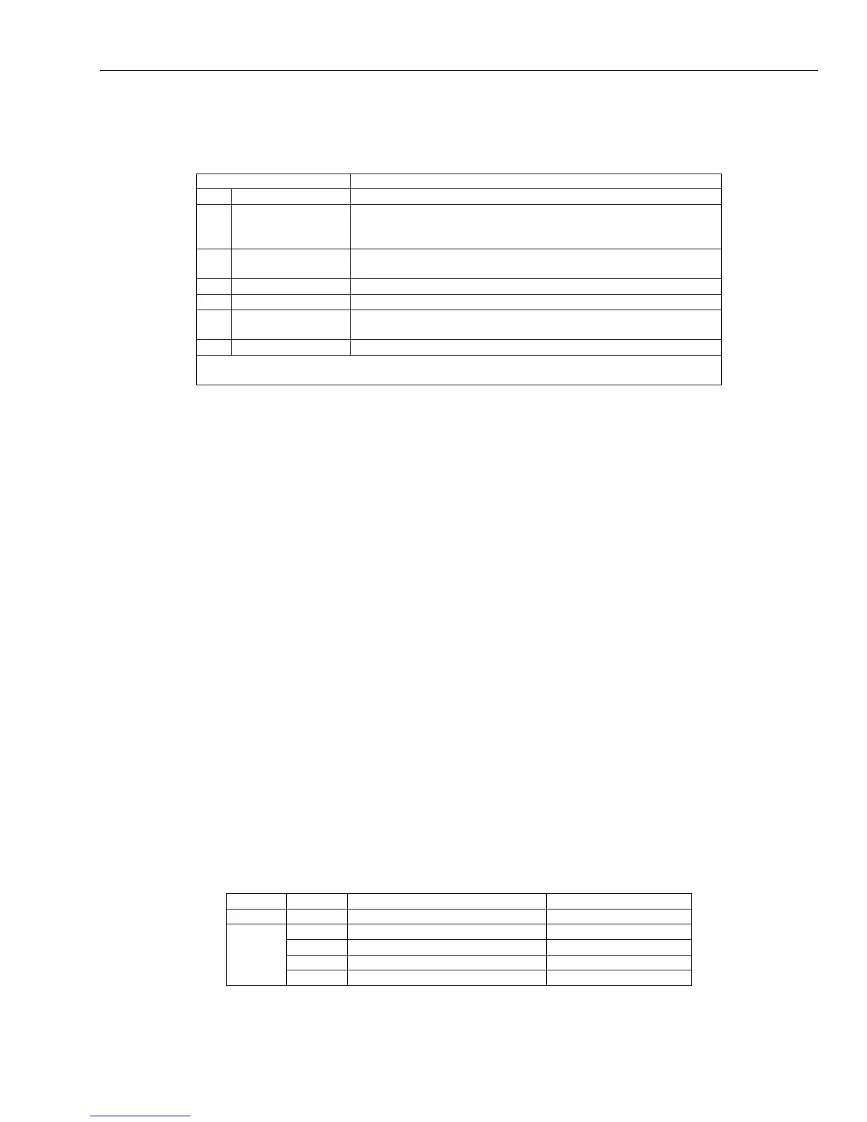
Attributes Description
1 Output Function Assign output type
2 Output Mode 1 = Latch - requires valid code to reset
2 = Reflex (Follow) - follows activation status of zones
3 = Pulse (001 - 3000 secs) - activates for programmed period
3 Output Polarity 0 = POS - 12V going to 0V in activation
1 = NEG - 0V going to 12V in activation
4 Diag. Recording Assigns output to be active during Diagnostic Test
5 Descriptor Assigns a descriptor of up to 12 characters for each output
6 Lighting 1 = Control (0=OFF, 1=Toggle, 2=Trigger)
2 = Show Status (0=OFF, 1=ON)
7 Output Groups Assign groups to the output
Note: Groups only appear if the Group option is enabled
(refer to option 63.1 = OPTIONS. Groups).
Table 6-18. Output Attributes
Selecting Outputs
RIO Outputs
On entering the option, the first output on the system is displayed; the output address, function and mode
are displayed on the top line, the polarity and assigned groups are displayed on the bottom line.
From the display of the first output, any output on the system can be displayed by pressing the A> or <B
keys or by entering the address of a specific output.
The output is selected for programming by pressing the ent key; the first output programming attribute
1=Op Function is displayed.
Trigger Header Outputs {Not Evaluated by UL}
There are six trigger outputs that can be used as communication triggers, but can also be used for any other
purpose. The output address and default function of these outputs are as follows:
0001 - Fire
0002 - Panic
0003 - Intruder
0004 - Set
0005 - Zone Omit
0006 - Confirm
Keypad Outputs
The keypad outputs are fully programmable. The address of the keypad output is the keypad address
prefixed with a star, for example the output for keypad 06 is *06. The function of keypad outputs default to
Entry/Exit Horn.
The valid addresses of the keypads on each of the panels and the respective output addresses are indicated
in the following table:
Panel Line Address Output Addresses
GX-48 1 0 – 2, B, C, D, E & F (NOTE) 10-12, 15-19
1 0 – 2, B, C, D, E & F (NOTE) 10-12, 15-19
2 0 – 6 & F 20-26, 29
3 0 – 6 & F 30-36, 39
GX-520
4 0 – 6 & F 40-46, 49
Table 6-19. Addresses of Valid Keypad Outputs
 Loading...


