GX-Series Control Panel Installation and Setup Guide
2-12
Wiring Zones
The zones on GX-Series panels can be Double Balanced (default) or End of Line. Zones can be programmed
with different resistance ranges for zone status activation (see Parameter 51.46 = Parameters.Zone
Resistance). Refer to Table 2-7 (Double Balanced) or Table 2-9 (End of Line) for details of the zone
resistance and resulting conditions. The system default is Option 9, giving fault monitoring on 1k double
balanced wiring.
NOTE: The circuit debounce time (the period the zone must remain in a state to register a change in condition) is
300 milliseconds by default.
Option 01 - 1k Option 03 – 2.2k Option 05 – 4.7k Option 07 – 5.6k Option 09 - 1k Fault
Tamper S/C 0 – 800 0 – 1800 0 – 3700 0 -1400 0 - 800
Low Res 800 – 900 1800 – 2000 3700 – 4200 1400 – 2800 800 - 900
Normal 900 – 1200 2000 – 2500 4200 – 5500 2800 – 8400 900 -1200
High Res 1200 – 1300 2500 – 2700 5500 – 6500 8400 – 9800 1200 - 1300
Open 1300 – 12000 2700 – 12000 6500 – 19000 9800 – 12600 1300 - 3500
Fault - - - - 3500 - 4500
Masked 12000 – 19000 12000 – 15000 19000 – 22000 12600 – 22000 4500 - 19000
Tamper O/C 19000 – infinity 15000 – infinity 22000 – infinity 22000 – infinity 19000 - infinity
Table 2-6. Double Balanced Zone Resistance and Conditions
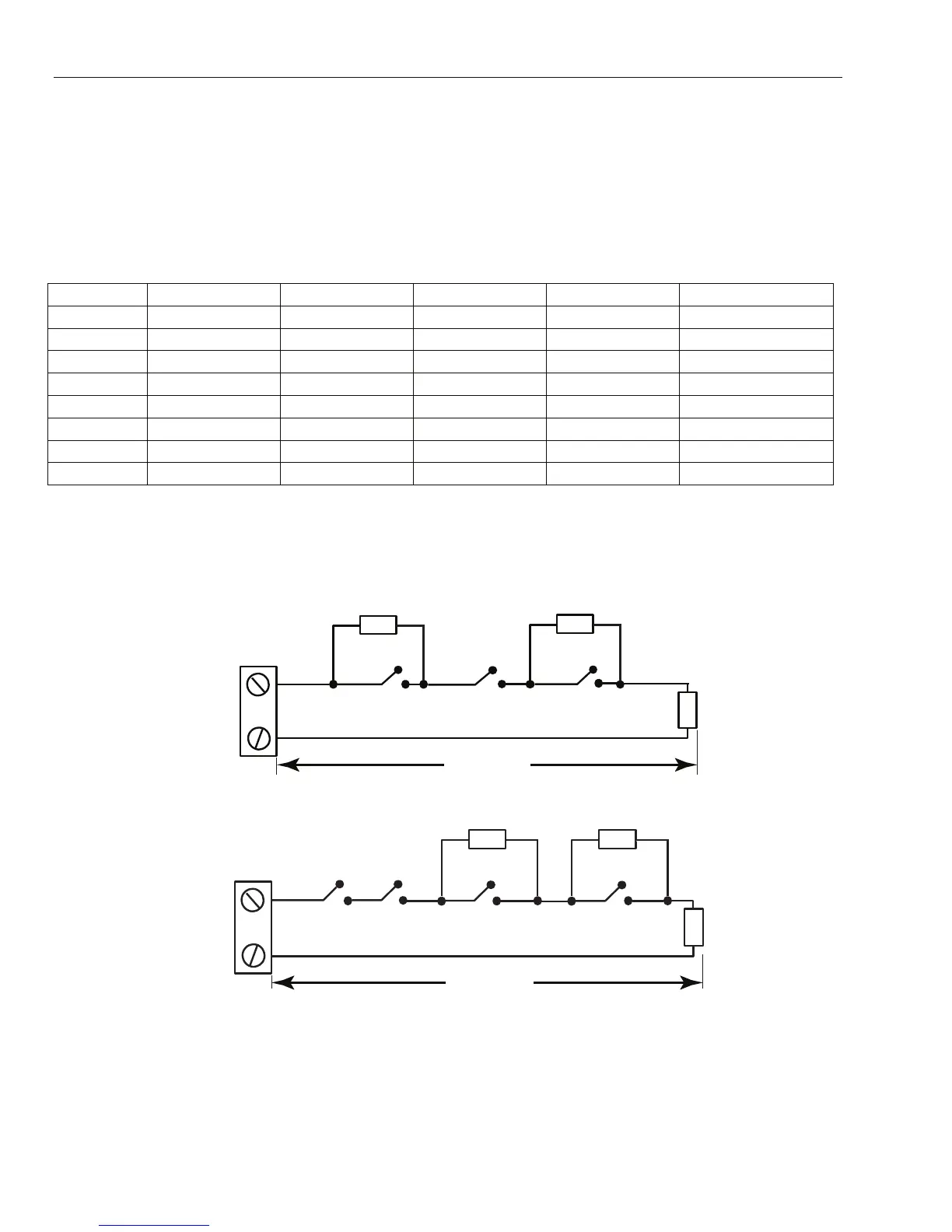
Option 09 - 1k Fault Double-balanced (default)
The wiring in Figure 2-12 should be used if the detector uses combined fault and mask signaling. A mask
condition is generated if an alarm and fault are signaled at the same time. Alternatively, if the detector has
separate fault and mask indications then the wiring in Figure 2-13 should be used.
Zone
1k
328 ft (100 m)
Tamper N/C
1k
Alarm N/C Fault N/C
3k
GX-012-V1
Figure 2-12. Option 09 - Double balanced 1k Fault Monitoring Wiring
Zone
Tamper N/C
1k
Alarm N/C
Fault N/C
3k 12k
Anti-mask N/C
GX-013-V2
328 ft (100 m)
Figure 2-13. Option 09 - Double balanced 1k Fault/Mask Monitoring Wiring
NOTES: For UL Installations, use 1K Ohm single EOL resistor configurations; the maximum loop impedance is 100 Ohms.
N/C = Normally Closed.
 Loading...


