TZ-3 TOTALZONE® ZONE CONTROL PANEL
68-0223-2 12
Certain conditions can han
u
the micro
rocessor. To reset
it,
ress and release the Boot button. The s
stem reboots and
enters the Pur
e mode.
Discharge Air Temperature Sensor
The Dischar
e Air Tem
erature Sensor
not included
is a
su
l
-duct-mounted tem
erature
robe used to control
ca
acit
and
revent over-heatin
or coil-icin
. The sensor
attaches to the TL terminals on the
anel.
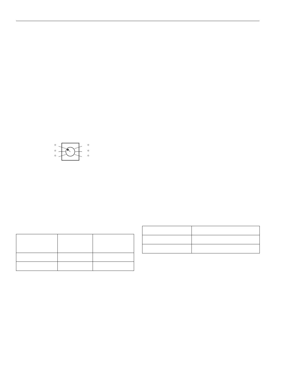
Set the hi
h limit tem
erature on the maximum tem
erature
dial on the
anel, located left of the sta
e timer. See. Fi
. 19.
Set the tem
erature from 110 °F to 160°F in ten-de
ree
increments. The recommended settin
for fossil fuel/ electric
s
stems is 160°F
default factor
settin
. For heat
um
s
stems, the recommended settin
is 120F.
The coolin
tem
erature limit can be set at 40°F or 48°F.
Fig. 19. Maximum temperature dial.
IMPORTANT
Be sure the Discharge Air Temperature Sensor wir-
ing does not run parallel with line voltage wiring
unless more than 12 in. of separation exists or
shielded cable is used.
Use DIP switch 2 to chan
e coolin
limit settin
s.
If the s
stem tri
s due to exceedin
a hi
h or low tem
erature
limit, the heatin
or coolin
s
stem shuts down and the fan
continues runnin
to
ur
e the conditioned air from the
lenum.
When the low limit is tri
ed, the Cool LED flashes until it
resets. When the hi
h limit is tri
ed, the Heat LED flashes
until it resets.
Once the tem
erature recovers b
ten de
rees, the
e
ui
ment run resumes.
When the Zone-A-Lone switch is in the occu
ied
osition and
the OC/OC terminals are not used, the s
stem functions as a
normal zone control s
stem. When switched to the
unoccu
ied
osition, all dam
ers are o
ened and all re
uests
for heat, cool, or fan, exce
t from zone one, are not honored.
The zone one thermostat becomes the controllin
thermostat
for the entire s
stem. Durin
lon
unoccu
ied
eriods, one
thermostat can be set back instead of ad
ustin
each zone
thermostat in the buildin
.
The T8601D2027 and T8611G2051 include two OC terminals.
When wired to the TZ-3 OC terminals, and with the Zone-A-
Lone switch in the occu
ied
osition, the board enters the
unoccu
ied mode durin
the Leave and Slee
ro
rams. This
feature re
uires two extra wires to the Zone 1 thermostat.
Circuit Breaker Protection
A built-in thermal circuit breaker
rotects the TotalZone
anel.
This circuit breaker
rotects the
anel a
ainst shorts in the
thermostat and dam
er wirin
and the remote occu
ied/
unoccu
ied switch. It does not
rotect a
ainst shorts in the
wirin
of the HVAC e
ui
ment into the
anel.
When the circuit breaker is tri
ed, none of the LEDs
illuminate and the
ellow rectan
ular com
onent located to
the left of the TR1 and TR2 terminals is hot to the touch.
Remove
ower to the
anel for at least ten seconds to allow
the circuit breaker to cool off and reset. To eliminate the short,
verif
the dam
ers and thermostat wirin
.
The s
stem blower can be set to come on with a call for heat
as re
uired for h
dro-air, heat
um
, or electric heat s
stems.
Set the blower usin
DIP switch 8.
TotalZone Add-A-Zone Panels
Usin
TotalZone Add-A-Zone Panels, the s
stem can be
ex
anded to u
to 30 zones. There are three models: TAZ-1,
one zone; TAZ-2, two zone; and TAZ-3, three zone. Two wires
are re
uired to connect the TAZ to the TZ-3.
IMPORTANT:
When multiple panels are used, it is important that
the transformers be in-phase. Check the phasing by
measuring for 24V across the TR2 transformer termi-
nals on each panel. There should be 0 Vac. If not,
reverse the TR1and TR2 transformer wires on one of
the panels and recheck.
See Fi
. 13 and the TAZ installation instructions for more
information.
Dip Switch Status
Cooling
Temperature
Limit
2 Off 40°F
2 On 48°F
130 F
MAXIMUM
TEMPERATURE
M19079
120 F
110 F
140 F
150 F
160 F
DIP Switch 8 Fan Control
Off HVAC s
stem
On Fan on in heat
 Loading...