V48A,F,J; V88A,J DIAPHRAGM GAS VALVES
60-2080—9 10
4. If there is still no voltage at the actuator, make sure all
the appropriate contacts in the thermostat (or
controller), limit(s), and flame safeguard control are
closed. If one or more is open, determine the cause(s)
and correct the con-dition(s) before proceeding.
5. If there is proper voltage at the valve actuator but the
valve still does not open, first check that the gas
pressure at the valve is normal. Then make sure that
the bleed line is unobstructed.
6. If the gas pressure and bleed line are okay but the valve
still does not open, replace the coil assembly. (Refer to
the Specifications section for the proper part number,
and to the Service Information section for the proper
procedure.)
7. If you replace the coil assembly and the valve still does
not open, replace the valve.
If the valve will not close when one or more of the
appropriate contacts in the thermostat (or
controller), limit(s), or flame safeguard control is
open:
1. Make sure that the gas flow is in the direction of the
arrow on the valve body.
2. Make sure the valve actuator is wired in the correct
circuit. Open the master switch to remove power from
the valve actuator. If the valve closes now, the actuator
may not be wired properly.
3. Look for a short in the electrical circuit.
SERVICE INFORMATION
WARNING
Electrical Shock Hazard.
Can cause severe injury or death.
1. Only qualified service technicians should attempt to
service or repair flame safeguard controls and
burner systems.
2. Open the master switch before replacing the coil
assembly or the valve. Line voltage is present in the
electrical circuits to the valve.
Scheduled Inspection and Maintenance
A schedule should be set up and followed for periodic
inspection and maintenance for the burner and all other
controls and the valve(s). Refer to the instructions for the
flame safeguard control for more information.
Replacing the coil assembly (Figs. 12
through 15)
1. Open the master switch to disconnect all power to the
valve actuator.
2. Loosen the cover screw in the front of the actuator
housing (Fig. 12) and remove the housing cover.
3. Disconnect the external wires from the two internal
black leadwires (Fig. 12).
4. Remove the two torx screws inside the actuator housing
(Fig. 13) and lift off the housing.
5. Remove the holding nut from the top of the coil
assembly (Fig. 13).
6. Lift the coil assembly straight up and off the plunger
tube assembly (Fig. 14).
7. Snap out the wraparound metal cover and remove the
metal base (Fig. 15). Save these parts for the
replacement coil.
8. Carefully unhook the cardboard insulator (Fig. 15) and
remove it. Save the insulator for the replacement coil.
9. Make sure the new coil assembly has the same part
number as the old one; then discard the old coil
assembly.
10. Wrap the cardboard insulator around the new coil
assembly and carefully hook it together around the two
black leadwires (Fig. 15).
11. Insert the two black leadwires through the opening in
the metal base, and insert the new coil assembly into
the metal base (Fig. 15).
12. Snap the wraparound metal cover into place around the
new coil assembly (Fig. 15).
13. Slip the new coil assembly over the plunger tube
assembly (Fig. 14).
14. Replace the holding nut on top of the coil assembly (Fig.
13) and tighten it securely.
15. Replace the actuator housing and tighten the two torx
screws holding it in place (Fig. 13).
16. Reconnect the external wires to the two internal black
leadwires (Fig. 12).
17. Replace the housing cover, and tighten the cover screw
holding it to the actuator housing (Fig. 12).
18. Close the master switch.
19. Test the valve to make sure it opens and closes as
described in the Operation section.
20. Verify proper operation after servicing.
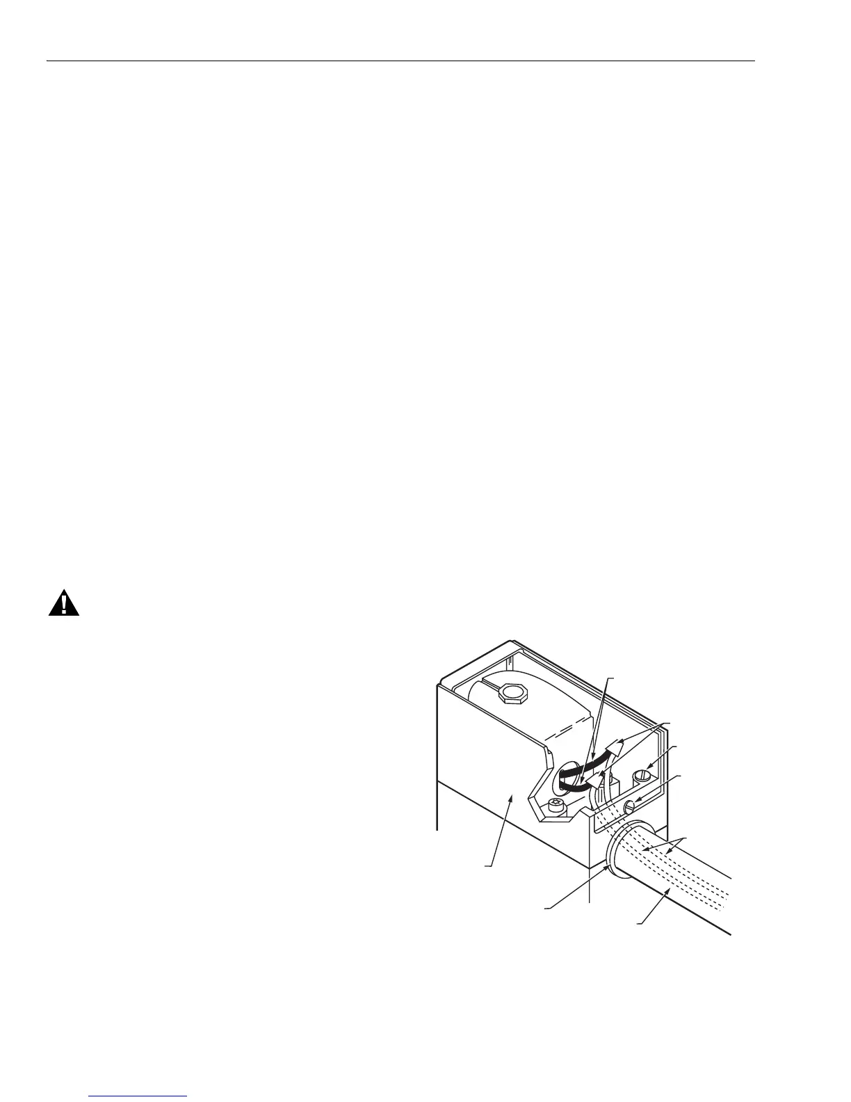
Fig. 12. Wiring connections and actuator housing.
M7302
6 IN. [152.4 MM] INTERNAL
BLACK LEADWIRES
(FROM COIL)
SOLDERLESS
CONNECTORS
GROUNDING
SCREW
EXTERNAL
WIRES
ACTUATOR
HOUSING
OPENING IN
ACTUATOR
HOUSING
CONDUIT
(IF REQUIRED)
COVER
SCREW

 Loading...


