V48A,F,J; V88A,J DIAPHRAGM GAS VALVES
60-2080—9 6
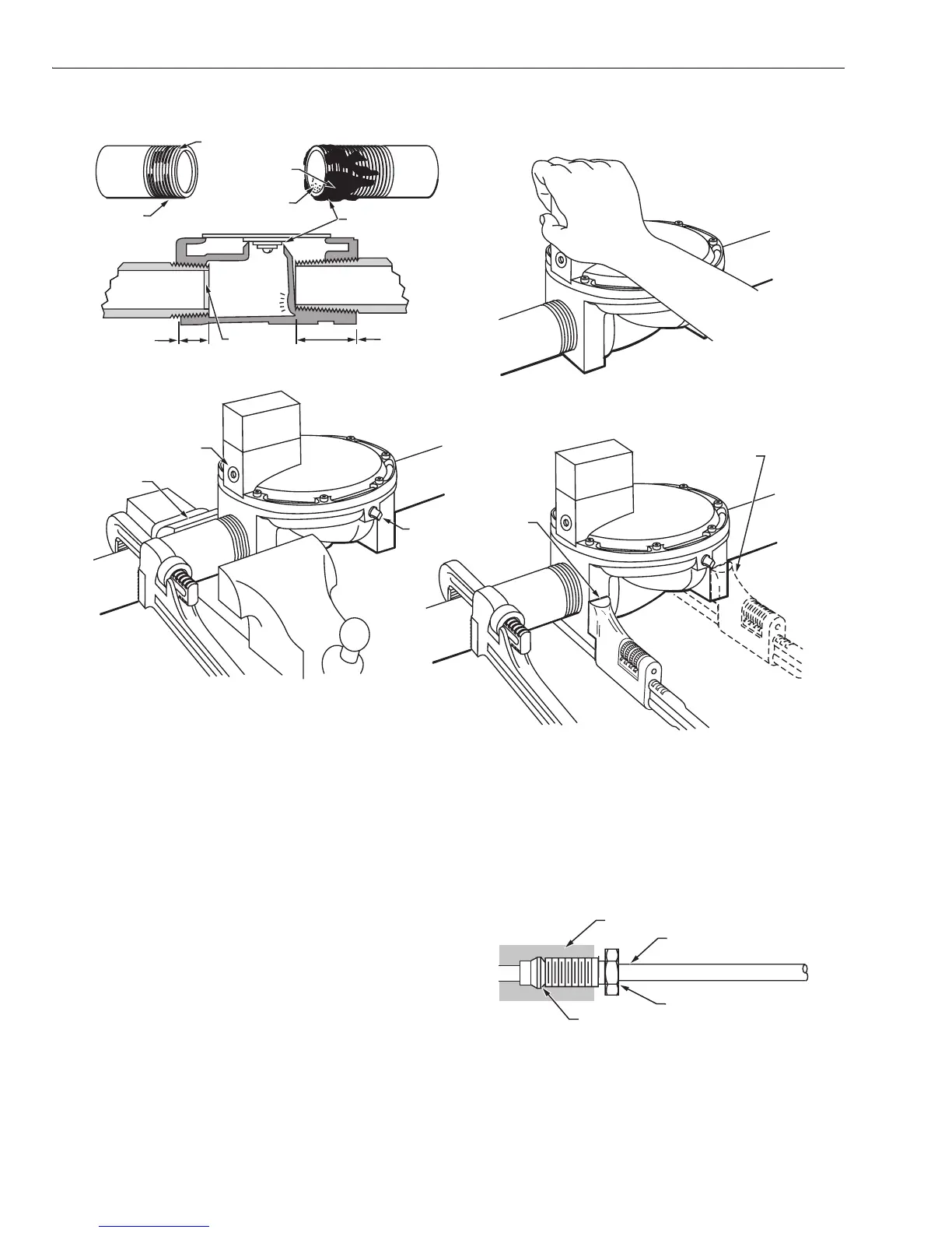
Fig. 3. Preparing piping and installing valve.
IMPORTANT:
When replacing a valve, cut off old compression
fitting and replace with a new compression fitting.
Never use the old compression fitting because it may
not provide a tight gas seal.
3. Push tubing into the pilot gas tapping on the outlet end
of the valve until it bottoms. While holding tubing all the
way in, slide fitting into place and engage threads—turn
until finger tight. Then use wrench and tighten one turn
beyond finger tight.
4. Connect other end of tubing to pilot burner according to
pilot burner manufacturers instructions.
5. If required, connect the tubing to bleed gas tapping
(Fig. 3 and 4) as described in step 3. Connect other end
of bleed tubing to main burner or to outside atmosphere.
WIRING
1. Disconnect the power supply before making wiring
connections to prevent electrical shock and equipment
damage.
Fig. 4. Connecting tubing to pilot for bleed gas tapping.
2. All wiring must comply with applicable electrical codes,
ordinances, and regulations. Use NEC Class 1 (line
voltage) wiring.
WRONG
WRONG
WRONG
RIGHT
2 CLEAN
THREADS,
MODERATE
AMOUNT
OF DOPE
EXCESS DOPE
MAY BLOCK
DISC OFF
VALVE
SEAT
LOOSE CHIPS
NEVER USE VALVE
AS A HANDLE
NORMAL FULL
THREAD
RIGHT
RIGHT
NORMAL FULL
THREAD
REAM PIPE,
BLOW OUT
CHIPS (THEY MAY
LODGE ON SEAT)
TOO LONG,
DISTORTS VALVE
SEAT
WRONG
TOO LONG,
DISTORTS VALVE
SEAT
VISE GRIPS
END NEXT
TO PIPE
BEING
INSERTED
RIGHT
WRENCH
CORRECTLY
APPLIED
NEXT TO
PIPE BEING
INSERTED
BLEED
GAS
TAPPING
PILOT GAS
TAPPING
WRENCH HERE
STRAINS VALVE BODY
M7299
SLEEVE CLINCHES AROUND TUBING
AS NUT IS TIGHTENED
COMPRESSION FITTING
GAS FLOW
TUBING
GAS VALVE
M7300
 Loading...


