Do you have a question about the Honeywell V5055A-E and is the answer not in the manual?
The V5055A-E Industrial Gas Valve is a crucial component in industrial and commercial burner applications, designed to ensure safe and efficient operation. This series of fluid power actuators, including models V4055, V4062, and V9055, provides reliable control over gas flow.
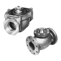
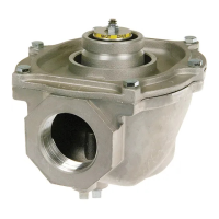
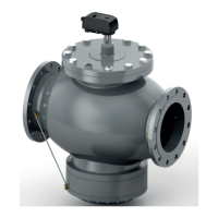
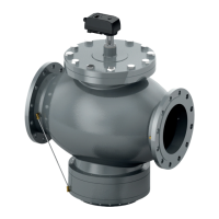
The V5055A-E valve is an industrial gas valve designed for on-off service, meaning it controls the flow of gas by either fully opening or fully closing. It can be configured for slow-opening, hi-lo-off, or modulating service, depending on the specific application requirements. The valve is typically used in conjunction with a V5055D Actuator to provide proof-of-closure switch and a valve seal overtravel interlock, enhancing safety and operational reliability. The V5055A,C,D,E valves are specifically designed for on-off service, while the V4055, V4062, and V9055 Fluid Power Actuators are used in combination with the V5055B,C,D,E valves to provide various control functionalities. The V5055D,E valves are suitable for high-pressure applications.
The V5055A-E valves are available in sizes ranging from 3/4 to 3 inches, with NPT (National Pipe Taper) or BSP-PL (British Standard Pipe Parallel) thread connections. Models are also available with BSP-PL threads, and V5055A,B,C valves are available in 4-inch size with flange connections. Most models feature 1/4 inch upstream and downstream top and plug, with BSP-PL thread models having 1/4 inch upstream tap and plug. The valve body is made of die-cast aluminum.
The maximum operating pressure differential for these valves is 75 psi (517.1 kPa). The valve's capacity is measured in Btu/h (from burner nameplate) or Btu/h (from gas utility). For specific gas types, the capacity can be calculated by multiplying the specific gravity average by a multiplier. For instance, LP-Propane has a multiplier of 0.647, and LP-Butane has a multiplier of 0.569.
The V5055 series valves have specific I.A.S. rated capacities depending on the valve size. For example, a 3/4-inch valve has a capacity of 665 cfh (18.8 cu m/hr), while a 4-inch valve has a capacity of 10200 cfh (288.8 cu m/hr). The upstream tapping and plug are 1/4 in. NPT or BSP-PL as standard. The downstream tapping and plug are 1/4 in. NPT on most domestic models. The valve dimensions vary by size, with a 3/4, 1, 1-1/4, 1-1/2 in. valve weighing 4 lb (1.8 kg), and a 4 in. valve weighing 28 lb (12.7 kg).
The V5055A-E valves are designed for ease of installation and operation. Before installation, it is crucial to turn off the gas supply and disconnect power to the valve actuator. The valve should be installed so that the arrow on the valve body points in the direction of gas flow. The final position of the valve and actuator must allow for damper linkage, if required.
For 3/4 through 3-inch valves, installation involves using two clean pipe dope threads, two clean pipe dope washers, and two clean pipe dope nuts. For 4-inch valves, installation requires two threaded companion flanges, two gaskets (included with valve), and 16 bolts (with washers and nuts) for models 4-inch V5055 valve. The flanges and gasket are placed on each end of the valve as shown in Fig. 6. The pipe dope is then screwed into the threaded flanges, and the valve and pipes are properly shown in Fig. 4 and 5.
After installation, the actuator must be mounted on the valve body, and the electrical and linkage connections must be completed according to the instructions packed with the actuator.
The valve operation involves checking for proper functionality. The V5055 Industrial Gas Valve is operated by a V4055, V4062, or V9055 Fluid Power Gas Valve Actuator. The valve opens when the actuator is energized and closes when power is removed. When closed, the valve will be off against the rated close-off pressure with no power applied.
Regular maintenance is essential to ensure the longevity and safe operation of the V5055A-E valves. This includes periodic inspection and testing.
Valve Leak Test: A critical maintenance procedure is the valve leak test. This test is performed by a qualified person who has received training on the proper procedure. The test involves checking for gas leakage at various points in the system. The steps include:
Replacement of Seals: When removing the bonnet to inspect and clean the valve, install new seals. The seals should be coated with grease prior to installation. Failure to properly position and seat the seals in the valve body may result in a hazardous gas leak. After the bonnet assembly is installed, or if the bonnet is removed for any reason, check for gas leakage around the bonnet seal. Turn on the gas at the manual valve. Paint the seal area with a rich soap and water solution. Bubbles indicate a gas leak. If a leak is detected, check to see that the bonnet screws are tight. If necessary, turn off the gas again and remove the bonnet to be sure the seals are properly seated.
The bonnet valve may be replaced without removing the valve body from the gas line. Do not disassemble the valve bonnet assembly; the valve seal is not replaceable.
Troubleshooting: If the valve fails to operate correctly, common issues include:
Regular checks and adherence to the maintenance schedule will help prevent these issues and ensure the safe and efficient operation of the V5055A-E Industrial Gas Valve.
| Brand | Honeywell |
|---|---|
| Model | V5055A-E |
| Category | Control Unit |
| Language | English |