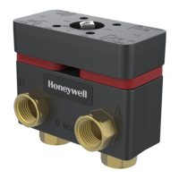
V9055A,D MODULATING FLUID POWER GAS VALVE ACTUATOR
60-2311-11 4
a
Valve size using accessory pipe adapter fitting.
b
Without flanges.
Approvals:
Underwriters Laboratories Inc. Listed: File No. MH1639, Guide
No. YI0Z.
Factory Mutual Listed: Report Nos. 20835 and 24061
Canadian Standards Association certified: General Listed file
numbers 158158 Class 3371
For U.S.A. and Canada: certified 60 Hz models only.
Swiss Re (Formerly GeGap/IRI) Acceptable.
Accessories:
133568 Auxiliary Switch.
7616BR Crank Arm.
133569 Proof-of-closure Switch Bag Assembly. Must be
used with V5055C or E.
203422C Adapter Board—Used to control V9055 Actuator with
4-20 dc mA input.
INSTALLATION
Electrical Shock Hazard.
Can cause serious injury, death or equipment damage.
1. Disconnect power before connecting wiring.
2. Assure that wiring complies with applicable electrical
codes and ordinances.
3. Be sure that power supply is the same as that
stamped on the nameplate of the device.
4. Be sure only a trained, experienced, flame safeguard
control serviceman installs or services this device.
5.Assure that loads connected to the auxiliary switch, if
used, do not exceed the ratings given in the
Specifications section.
NOTICE: Per Industry Standards, the actuator is required a
conduit seal or a cable type that is sealed be installed in a
device that can result in a flammable liquid flow through a
conduit or cable to an electrical ignition source in the event of a
seal leakage or diaphragm failure.
IMPORTANT
1. Do not attempt to use the V9055 with one of the
adapters that connects the V4055 Actuator to the
older V5034 Valves. The V9055 cannot be used with
a V5034 Valve. When replacing a V9034 Actuator
with a V9055, the V5034 Valve must be replaced with
a V5055/V5097 Gas Valve.
2. Connect terminals R, W, and B only to Series 90 pro-
portioning controller. Do not apply any voltage to
these terminals.
3. Avoid mounting actuator upside down if water is likely
to drip on it. In this position, water can become
trapped in the electronics compartment.
When Installing This Product…
1. Read these instructions carefully. Failure to follow them
could damage the product or cause a hazardous condi-
tion.
2. Check the ratings given in the instruction and on the
product to make sure the product is suitable for your
application.
3. Installer must be a trained, experienced service techni-
cian.
4. After installation is complete check product operation as
provided in these instructions.
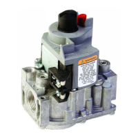
Valve Installation
The actuator is mounted directly on the V5055/V5097 Valve
after the valve is installed in the gas supply line. Refer to the
instructions packed with the V5055/V5097 Valve for details of
installation. When installing the valve, be sure that:
1. Sufficient clearance is left for installation and service of
the actuator.
2. Ambient temperatures at the valve location will remain
within the rated ambient range.
3. The position of the valve permits hookup to the damper if
one is controlled.
IMPORTANT:
When a damper crank arm is used with a NEMA 4
actuator that is exposed to ice or sleet, a suitable
shield must be installed to prevent ice or sleet buildup.
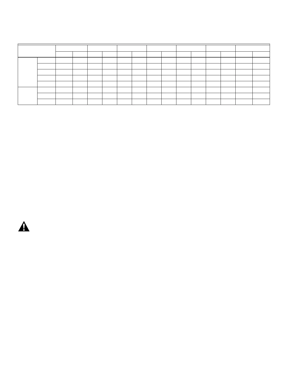
Table 4. V9055/V5097 dimensions in inches. (mm)
Valve Size
a
(in.)
Dim. A Dim. B Dim. C Dim. D
b
Dim. E Dim. F Dim. G
in. mm in. mm in. mm in. mm in. mm in. mm in. mm
Small Body 3/4 11-1/8 282.6 2-3/4 69.9 8-3/16 208.0 5-5/8 142.9 2-1/2 63.5 4-13/16 122.2 13-3/16 335
1 11-1/8 282.6 2-3/4 69.9 8-3/16 208.0 5-5/8 142.0 2-1/2 63.5 4-13/16 122.2 13-3/16 335
1-1/4 11-1/8 282.6 2-3/4 69.9 8-3/16 208.0 5-5/8 142.9 2-1/2 63.5 4-13/16 122.2 13-3/16 335
1-1/2 11-1/8 282.6 2-3/4 69.9 8-3/16 208.0 5-5/8 142.9 2-1/2 63.5 4-13/16 122.2 13-3/16 336
2 11-1/8 282.6 2-7/8 73.0 8-3/16 208.0 5-5/8 142.9 2-1/2 63.5 7-19/32 192.9 13-3/16 335.0
Large Body 2 11-3/4 298.5 3-3/8 85.7 8-3/8 212.7 9-7/16 239.7 4 101.5 7-19/32 192.9 13-3/8 339.7
2-1/2 11-3/4 298.5 3-3/8 85.7 8-3/8 212.7 9-7/16 239.7 4 101.5 7-19/32 192.9 13-3/8 339.7
3 11-3/4 298.5 3-3/8 85.7 8-3/8 212.7 9-7/16 239.7 4 101.5 7-19/32 192.9 13-3/8 339.7

 Loading...