V9055A,D MODULATING FLUID POWER GAS VALVE ACTUATOR
7 60-2311-11
OPERATION
To function as intended, the V9055 must be connected to a
properly sized valve. The proper sized V5055/V5097B Gas
Valve with characterized guide is recommended for optimum
control and low-fire repeatability. Too large of a valve will not
properly modulate the gas flow. When the actuator is
energized, it will drive at least to the adjusted low-fire position.
The distance it will open beyond this low-fire position depends
on the demands of the modulating controller.
When the controller calls for no heat, the actuator will modulate
the valve to the low-fire position. When power to the actuator is
interrupted, the valve will completely close.
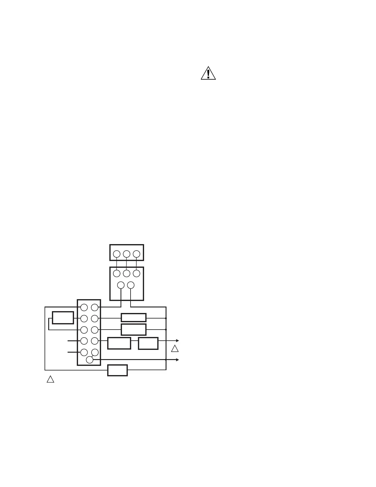
Fig. 6 shows the V9055 in a typical flame safeguard control
system.
CHECKOUT AND SERVICE
Checkout
IMPORTANT
Only a trained, experienced flame safeguard control
technician should service or repair this control.
After the valve installation is complete, cycle the valve a few
times with the manual fuel shutoff cock closed before testing
the system in actual operation.
Fig. 6. V9055 connected to R4795 in typical application.
Service
The actuator is not field repairable except for replacing the
auxiliary switch. See Install Accessory Switches section for the
procedure.
Do not disassemble the valve actuator. Perform the following
checks before removing and replacing the V9055 Gas Valve
Actuator.
1. With manual gas valve closed, energize the V9055 and
check for voltage on terminals 1 and 2. Actuator should
modulate to the low-fire position.
Equipment Damage Hazard.
Improper wiring can damage the equipment and cause
injury to personnel.
Label all wires prior to disconnection when servicing
valves. Wiring errors can cause improper and
dangerous operation. Verify proper operation after
servicing.
2. Disconnect the leads from the modulating controller (ter-
minals W,R, and B). Connect a manual potentiometer,
color-to-color, to terminals W, R, and B on the actuator.
With the valve energized, use the potentiometer to open
and close the actuator. It should run from the low-fire
position and to the fully open position.
If the actuator fails to operate properly, replace it:
1. Turn off the gas supply at the manual shutoff valve
located upstream from the valve(s) being serviced.
2. Shut off all electrical power to the valve actuator(s).
3. Mark and disconnect the wires from the actuator termi-
nals. Remove conduit and disengage the damper linkage
assembly (if applicable).
4. Loosen the two set screws from the valve to lift off the
actuator.
5. If the actuator is to be replaced and it did not leak
hydraulic fluid, skip to Step 11.
NOTE: It is good practice to inspect the inside of the
valve whenever the actuator is replaced. To do
so, remove the bonnet assembly, inspect the
valve and bonnet. If all is well, proceed to Step
7.
6. If the actuator leaked hydraulic fluid onto the valve (the
fluid is red), it must be cleaned off from the valve and
bonnet assembly.
a. Wipe off the outer valve body.
b. Remove the valve bonnet bolts and lift off the bonnet.
NOTE: V5055/V5097C and E Valves have additional
internal springs that will push the bonnet up as
the bolts are loosened.
c. Inspect the inside of the valve.
IMPORTANT
If fluid is present on the inside surfaces of the valve
body or bonnet surfaces, the bonnet assembly or
entire valve must be replaced. See Table 5 below for
the bonnet assembly part number.
d. If the inside surfaces are clear of hydraulic fluid,
clean the bonnet assembly and be sure to remove all
hydraulic fluid from the inside and outside of the
actuator mounting curb. This is the “cup-like” area
around the valve stem. Avoid using a cleaning solu-
tion as it may damage the rubber seals used in the
valve.
8
7
6
F
G
X
X
2
5
4
3
1
WRB
W
R
B
12
V9055
ACTUATOR
SERIES 90
PROPORTIONING
CONTROLLER
R4795 FLAME SAFEGUARD
PRIMARY CONTROL
1
1
POWER SUPPLY. PROVIDE DISCONNECT MEANS AND OVERLOAD
PROTECTION AS REQUIRED.
AIR
SWITCH
IGNITION
PILOT
VALVE
CON-
TROLLER
LIMIT
L1
(HOT)
L2
FLAME
DETECTOR
FAN
MOTOR
M7324
 Loading...