V9055A,D MODULATING FLUID POWER GAS VALVE ACTUATOR
5 60-2311-11
Install Accessory Switches (If Needed)
An spdt switch may be installed to operate an auxiliary load of
up to 1/2 hp. The switch may be adjusted to operate at any
point in the valve stroke. A proof-of-closure switch may also be
installed. The proof-of-closure switch must be used with the
V5055 C,E/V5097C,E (two seals) Valve to provide valve seal
overtravel interlock.
The spdt proof-of-closure switch is installed to make or break a
circuit when the valve is in the closed position. The switch is
not adjustable.
NOTE: Mark the actuator or valve to indicate any changes
made.
To install the switches, proceed as follows:
1. Remove the actuator faceplate (two screws).
2. Remove the silver-colored barrier to expose the actuator
stem.
3. Insert the auxiliary switch in the position indicated in
Fig. 3. Fasten with two screws through the actuator base.
4. Insert the proof-of-closure switch in the position shown in
Fig. 3. The proof-of-closure switch mounts against the
side of the actuator housing. The mounting holes are
spaced to mount the switch only in the correct position.
Fasten with two screws through the actuator base.
5. If only one switch is used, install the narrow barrier
included with the switch in the unused space.
6. Mount the actuator before making wiring connections
and adjustments to the switch.
Mount and Adjust Damper Crank Arm
IMPORTANT:
When a damper crank arm is used with a NEMA 4
actuator that is exposed to ice or sleet, a suitable
shield must be installed to prevent ice or sleet buildup.
The crank arm provides a maximum travel of 2-5/16 in.
(59 mm). For complete installation information, refer to the
instructions packed with the 7616BR Crank Arm.
Fig. 2. Crank Arm Operation.
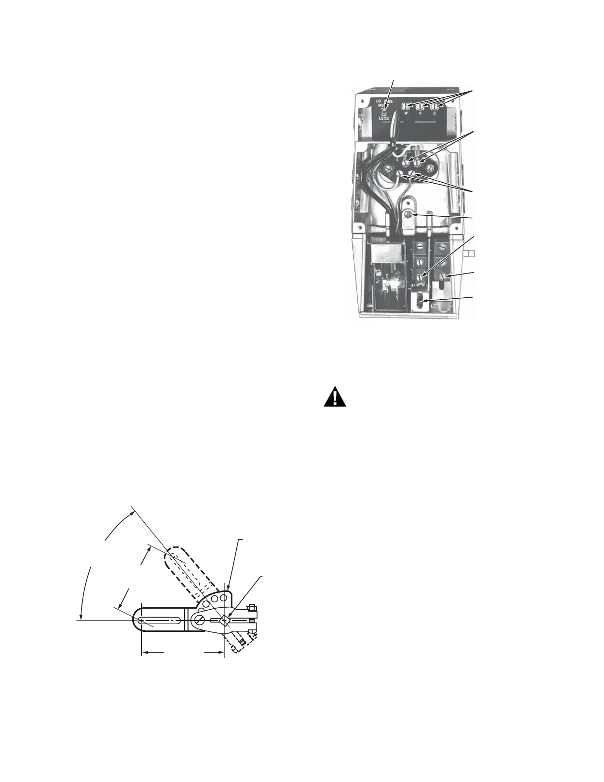
Fig. 3. Internal components and connections in V9055.
WIRING
Electrical Shock Hazard.
Can cause serious injury, death or equipment damage.
To prevent electrical shock or equipment damage
disconnect power supply before wiring.
All wiring must agree with applicable electrical codes and
ordinances.
Connect power supply to terminals 1 and 2 on the terminal
strip. Do not make any connections to the unmarked terminals
shown in Fig. 3.
NOTE: When replacing a V9034, remove the 24 volt trans-
former because V9055 has a built-in transformer.
When replacing a V9034 Actuator with a V9055,
replace the V5034 Gas Valve with a V5055/V5097
Valve.shown in Fig. 3.
NOTICE: Per Industry Standards, the actuator is required a
conduit seal or a cable type that is sealed be installed in a
device that can result in a flammable liquid flow through a
conduit or cable to an electrical ignition source in the event of a
seal leakage or diaphragm failure.
52 DEGREE
ANGULAR
ROTATION
MAXIMUM
TRAVEL
SHAFT
7616BR
DAMPER
ARM
M7322A
RADIUS
2-11/16 (68.3)
2-5/16 (58.7)
LOW FIRE ADJUSTMENT
CONNECTIONS
TO SERIES 90
PROPORTIONING
CONTROLLER
LINE VOLTAGE
POWER SUPPLY
CONNECTIONS
DO NOT MAKE ANY
CONNECTIONS
TO THESE TERMINALS
GROUND SCREW
AUXILIARY
SWITCH
PROOF-OF-CLOSURE
SWITCH
ADJUSTING SCREW
FOR AUXILIARY
SWITCH
M7320

 Loading...