EasyManua.ls Logo

Honeywell V9055A User Manual

Honeywell V9055A
8 pages
To Next Page IconTo Next Page
Page #1 background imageLoading...
Page #1 background image
PRODUCT DATA
60-2311-11
V9055A,D Modulating Fluid Power
Gas Valve Actuator
APPLICATION
The V9055 Gas Valve Actuator in combination with a V5055,
VE5000
a
or V5097 Gas Valve provides modulating control of
the gas supply to commercial and industrial burners.
a
VE5000 is a European manufactured and approved valve for
European use only.
FEATURES
Actuator opens the valve to the low-fire position when
energized. Actuator then modulates to meet firing rate
controller (Series 90) demand.
Actuator is equipped with an integral shaft that may be
used to drive a combustion air damper in unison with the
gas valve.
The V5055 or V5097 Gas Valve includes a yellow SHUT
indicator. The actuator includes a red OPEN indicator. The
indicators provide constant visual indication of valve
position.
Actuator can be used with all VE5000
a
, V5055 or V5097
Valve models; however, the V5055B or V5097B with
characterized guide is recommended for optimum control
and low-fire repeatability.
Ambient temperature range for 60 Hz models is -40°F to
125°F (-40°C to 53°C). Ambient temperature range for 50
Hz and 50/60 Hz models is -10°F to 125°F
(-23°C to 52°C).
Auxiliary 1/2 hp rated switch is available for field
installation.
Integral damper shaft provides a maximum of 20 lb
(9 kg) of force.
Valve and actuator may be mounted in any position.
Model is available with NEMA 4 (IP54) weatherproof
enclosure.
V9055D/V5055C,E and V9055D/V5097C,E combinations
available with proof-of-closure switch and two valve seals
(valve seal overtravel interlock) to meet specific code/
standard/insurer requirements.
Field addable adapter available for 4-20 dc mA control of
actuator.
When replacing a V9034 Actuator with a V9055, the V5034
Valve body must also be replaced with a V5055 or V5097
Gas Valve.
NOTICE: Per Industry Standards, the actuator is required a
conduit seal or a cable type that is sealed be installed in a
device that can result in a flammable liquid flow through a
conduit or cable to an electrical ignition source in the event
of a seal leakage or diaphragm failure.
Contents
Application ........................................................................ 1
Features ........................................................................... 1
Specifications ................................................................... 2
Ordering Information ........................................................ 2
Installation ........................................................................ 4
Wiring ............................................................................... 5
Adjustments ...................................................................... 6
Operation .......................................................................... 7
Checkout and Service ...................................................... 7
Question and Answer IconNeed help?

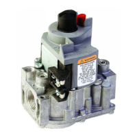
Do you have a question about the Honeywell V9055A and is the answer not in the manual?

Honeywell V9055A Specifications

General IconGeneral
BrandHoneywell
ModelV9055A
CategoryController
LanguageEnglish

Summary

Specifications

Damper Arm Rating

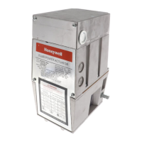
Details the maximum force for damper arms driven by the actuator under various temperature conditions.

Damper Shaft

Specifies the actuator shaft size and compatibility with damper arms, including optional return springs.

Ambient Temperature Rating

Defines the operational temperature range for 60 Hz and 50/60 Hz models.

Mounting Means

Describes how the actuator attaches to the valve and mounting flexibility.

Installation Dimensions

Provides diagrams and tables for physical installation dimensions of the actuator and valve.

Installation

Electrical Hazard Warnings

Details critical safety warnings related to electrical shock during installation and servicing.

Valve Installation

Guidance on mounting the actuator onto the valve, considering clearance and ambient conditions.

Damper Crank Arm Installation Note

Important consideration for NEMA 4 actuators exposed to ice/sleet when using a damper crank arm.

Wiring and Connections

Accessory Switches

Instructions for installing auxiliary and proof-of-closure switches for enhanced functionality.

Damper Crank Arm Mounting

Details on mounting and adjusting the damper crank arm for synchronized valve and damper operation.

Actuator Wiring

Guidance on connecting power supply and controller signals to the actuator, including safety precautions.

Operation and Adjustments

4-20 mA Input Adapter

Installation and hookup procedure for the 203422C adapter for 4-20 mA control input.

Low-Fire Setting Adjustment

Procedure to adjust the actuator's low-fire position for optimal burner lightoff and repeatability.

Auxiliary Switch Adjustment

How to adjust the auxiliary switch to operate at specific points within the actuator stroke.

Checkout and Service

System Checkout

Steps for verifying actuator operation and system functionality after installation and wiring.

Actuator Replacement

Detailed procedure for removing and replacing the V9055 actuator, including safety checks.

Bonnet Seal and Leak Check

Instructions for ensuring proper bonnet seal and leak prevention after service or replacement.

Related product manuals