8 Mounting and Connection Instructions Viewguard DUAL / AM BUS-2/BUS-1
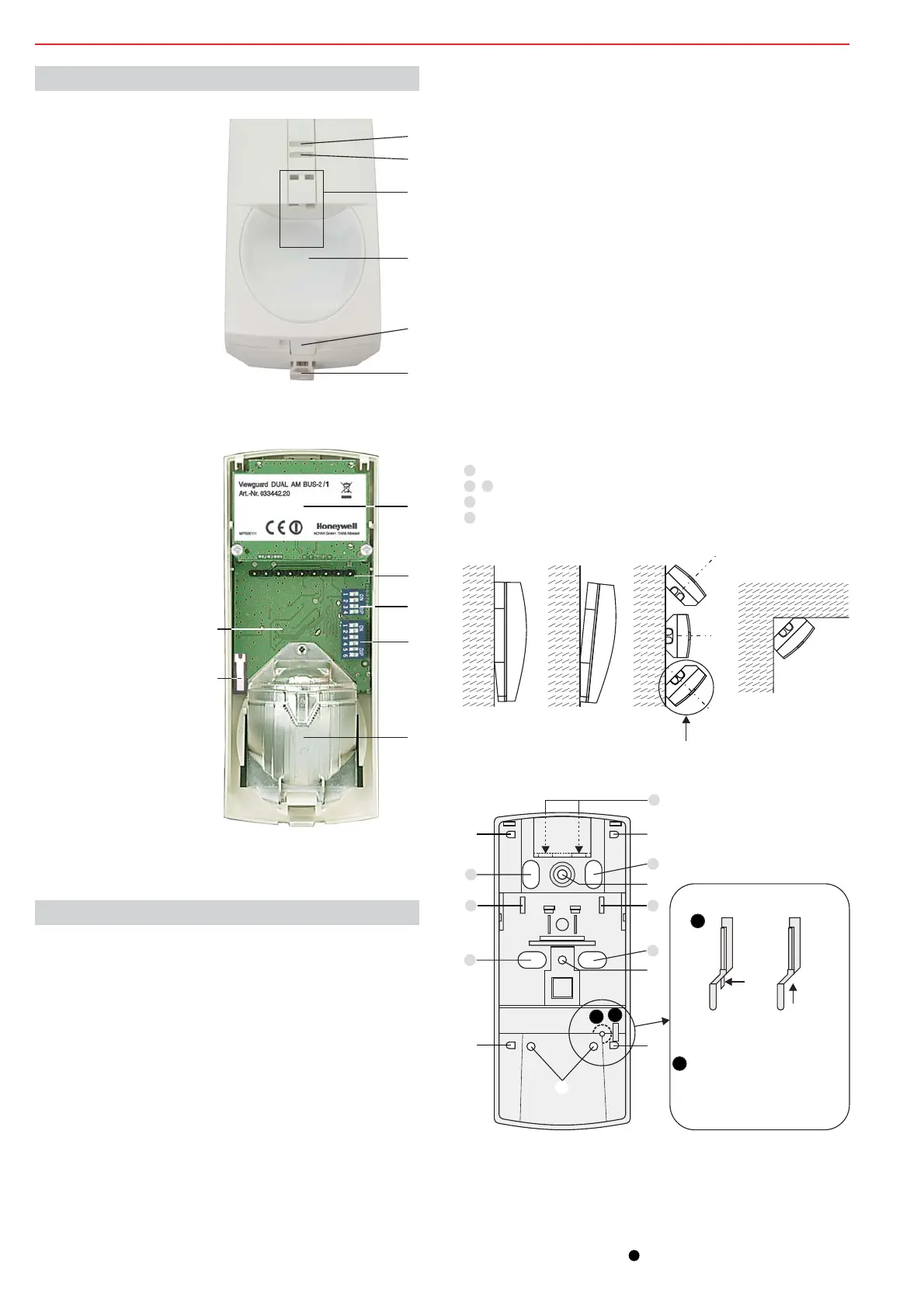
1 LED yellow
2 LED red
3 Anti-Mask sensor
(only AM detector)
4 Foil for mirror optics
5 Notch
6 Seal
Fig. 2
1 Microwave module
2 Plug connectors for terminal
strip
3
4 DIP switch S2
for BUS address
5 Mirror optics
DIP switch S1
for BUS-1 programming
(
)
(only AM detector)
7 PIR-/BUS module
DIP 5-digit switch with AM
detector
6 Tamper / backtamper
Fig. 3
5. Detector setup
6. Mounting
6.1 Mounting site
Maximum sensitivity is achieved when mounted crosswise to the hori-
zontal detection zones of the PIR sensors. Therefore, select a moun-
ting site that runs crosswise to the expected direction of motion. (See
Fig. 6).
Minimum distance to ceiling: 2 cm
Avoid:
* Mounting above radiators
* Mounting near air discharge openings (e.g. air conditioning
systems)
* Direct sunlight
* Mounting near to fluorescent lamps
* Mounting near to light bulbs
6.2 Mounting options (Fig. 4 and Fig. 5)
(Fig. 4/1)
Fix with 2 screws (Fig. 5- ).
(Fig. 4/2)
This position slightly reduces the range. We recommend this
position for small rooms.
Fix with 2 screws: At the bottom by 2 holes at the same height
(Fig.5- ).
(Fig. 4/3)
Fix through 2 holes above one another at the side (Fig. 5- ).
(Fig. 4/4)
Fix through 2 holes above one another at the side (Fig. 5- ).
When screwing down the back with 4 screws, it may become
taught and the front of the housing may no longer fit. To avoid this,
only fix the back on one side with 2 screws.
Should these mounting possibilities not suffice, the detector can be
mounted on the "Adjustable joint" (033390) or "Ball-and-socket set"
(033588), see "Accessories.
Detector on Adjustable joint .
Detector on Ball-and-socket set .
0° Vertical
Vertical at a 3° downward angle
Horizontal at a 45° angle to the left or right
Corner mounting
Attention! as per VdS and EN grade 2
not as per VdS und EN
Fig. 4
+/-0°
45°
45°
4/1 4/2 4/3 4/4
a)
b)
c)
Backtamper is not possible
6.4 Backtamper (see Fig. 5a)
(only AM detector)
Remove the pin at the tappet , if the backtamper is being used (see
illustration).
Required for installation according to EN 50131-2-4, grade 3.
a
b
Protective cover for
(o
Remove, when mounting as
per Fig. 4/3a) or 4/4
back-
tamper n the rear)
a
Tappet for backtamper
Tamper and
backtamper
Only tamper
with pin
without
pin
Fig. 5
A
B
C
B
C
D
D
a
b
Fig. 5a
A
B
C
C
D
6.3 Cable entry, strain relief (see Fig. 5)
For s.m. wiring
For f.m. wiring
For use with
For strain relief with cable strap
Adjustable joint
 Loading...