EasyManua.ls Logo

Honeywell VPI Series

Honeywell VPI Series
27 pages
To Next Page IconTo Next Page
Loading...
VPI PRESSURE INDEPENDENT
CONTROL VALVES AND ACTUATORS
INSTALLATION INSTRUCTION
® U.S. Registered Trademark.
Copyright © 2020 Honeywell Inc. All Rights Reserved. Printed in USA 31-00383-01, Rev A.
APPLICATION
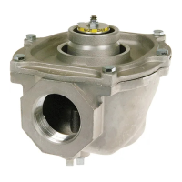
Honeywell pressure independent control valve (PICV) is
used in heating and cooling systems in applications
with Air Handling Units, Fan Coil Units, chilled ceilings,
zone control, or other terminal unit applications.
Honeywell VPI series provides modulating control with
full authority regardless of any fluctuations in the
differential pressure of the system. Honeywell VPI
series combines an externally adjustable automatic
balancing valve, a differential pressure control valve,
and a full authority modulating control valve.
Honeywell VPI series makes it simple to achieve 100%
control of the water flow in the building while creating
high comfort and energy savings at the same time. An
additional benefit is that no balancing is required if
further stages are added to the system, or if the
dimensioned capacity is changed. Energy-saving due
to optimal control, lower flow, and pump pressure.
Maximized ΔT due to faster response and increased
system stability
Application Notes
Valve sizing is important for correct system operation.
Undersized valves do not have sufficient capacity at
maximum load.
Proper Use
These valves are intended for use in chilled water and
hot water closed-loop applications only, with a media
temperature range of -20ºC to +120ºC (-4ºF to
+248ºF), and static pressures up to 580psi. Not
suitable for oil, combustible gases, or high-
temperature steam.
These valves are to be operated with the appropriate
and compatible Honeywell actuators only. Refer VPI
series PICV Product Datasheets for more details on
valve and actuators compatibility.
Water should be properly filtered, treated, and
conditioned for good operating performance, and
according to according to VDI 2035 with up to 50 %
Glycol (oxygen concentration less than 0.2 g/m3, pH
8...9.5; Fe<0.5 mg/kg; Cu<0.1 mg/kg). The installation
of strainers and filters is recommended. Do not use
manual balancing valves.
IMPORTANT: The presence of excessive iron oxide
(red rust) in the system voids the valve warranty.
Effective Flow Rate
The built-in differential pressure regulator makes fluid
flow through the valve independent of changes in
supply. The pressure regulator virtually eliminates
cavitation in the valve and decouples the control valve
from the effects of piping components such as
reducers and elbows.
Pressure independent control valves are sized to match
design coil flow regardless of coil connection size.
These valves eliminate the need to balance the system
for proper flow and allow chillers to be operated at
design temperature differential for maximum
efficiency at every load condition.
Flow Characteristic
The VPI series Pressure Independent Control Valves
have: Linear flow characteristic and can be converted
to an equal percentage in the actuator.

Table of Contents

Question and Answer IconNeed help?

Do you have a question about the Honeywell VPI Series and is the answer not in the manual?

Honeywell VPI Series Specifications

General IconGeneral
BrandHoneywell
ModelVPI Series
CategoryControl Unit
LanguageEnglish

Summary

APPLICATION

Application Notes

Important considerations for valve sizing and system capacity.

PROPER USE

EFFECTIVE FLOW RATE

FLOW CHARACTERISTIC

DECLARATION OF REACH CONFORMITY

Article 33 Communication

Information regarding lead content as per REACH regulation.

PREREQUISITE

PREPARATION

MECHANICAL INSTALLATION

Installation for DN15-32

Detailed steps for installing DN15-32 valve models.

Flow Setting

Procedure for setting the flow rate using the dial.

REPLACEMENT OF FLOW REGULATOR

Procedure to Remove the Flow Regulator

Steps for safely removing the flow regulator from the valve body.

Procedure to Install the Flow Regulator

Steps for correctly installing the flow regulator into the valve body.

INSTALLATION FOR DN40-50

FLOW SETTING FOR DN40-50

INSTALLATION OF DN50-250

ELECTRICAL INSTALLATIONS

Electrical Wiring for Actuators Compatible to DN15-50

Wiring diagrams for various actuator models used with DN15-50 valves.

INSTALLATION OF ACTUATORS COMPATIBLE WITH DN 15-50

Mounting Position

Guidance on mounting actuators for optimal IP54 rating.

Procedure to Remove the Actuator

Steps to safely remove an actuator from the valve.

INSTALLATION OF THERMOELECTRIC ACTUATORS (MLP41 TNA and MLP71 TNA)

Mounting Position

Guidance on mounting thermoelectric actuators for IP54 rating.

Procedure to Remove the Actuator

Steps to remove thermoelectric actuators using the release mechanism.

INSTALLATION OF ACTUATORS COMPATIBLE WITH DN50 - 250

Mounting Position

Guidance on mounting actuators for DN50-250 for IP54 rating.

Procedure to Remove the Actuator

Steps for removing actuators from DN50-250 valves.

DIP SWITCH SETTINGS

For Fail-safe actuators (MLE71 MAA and MLE75 MAB)

DIP switch settings for fail-safe actuator models.

For non - Fail-safe actuators (MLE71 MAA and MLE75 MAB)

DIP switch settings for non-fail-safe actuator models.

LED Status

Explanation of LED indicators and their meanings for actuators.

ELECTRICAL WIRING FOR ACTUATORS COMPATIBLE TO DN50-250

CONFIGURATION AND SETUP

Start Up Sequence

Initial sequence for actuator power-up and calibration.

Auto Cycle Sequence

Sequence to prevent valve jamming during inactivity.

Re-Calibration (MLP75 MAB)

Procedure for recalibrating the MLP75MAB actuator.

Manual Override (MLP75 MAB)

How to manually override the MLP75MAB actuator.

ELECTRICAL OVERRIDE (MLE75 MAB)

FAILSAFE MODE (MLE75 MAB)

MLP41 TNA AND MLP71 TNA (THERMOELECTRIC) ACTUATORS

Start-up Sequence

Initial startup sequence for thermoelectric actuators.

PROGRAMMING MENU

IN OPERATION FOR DN50 - DN250

ALARM MENU

AUTO-STROKE SEQUENCE FOR DN 50-250

MANUAL OVERRIDE

FAILSAFE MODE FOR DN 50-250

OPERATION & CHECKOUT

Related product manuals