W7212, W7213, W7214 ECONOMIZER LOGIC MODULES
5 63-2596—09
Mount the CO2 sensor according to the manufacturer
specifications. If not available, use the following guidelines:
1. Mount sensor in an area with unobstructed air
circulation.
2. Connect it to the AQ
and AQ1 terminals of the W7212
(see Wiring section for details).
3. Adjust the DCV potentiometer setpoint to correspond to
DCV voltage output at the threshold.
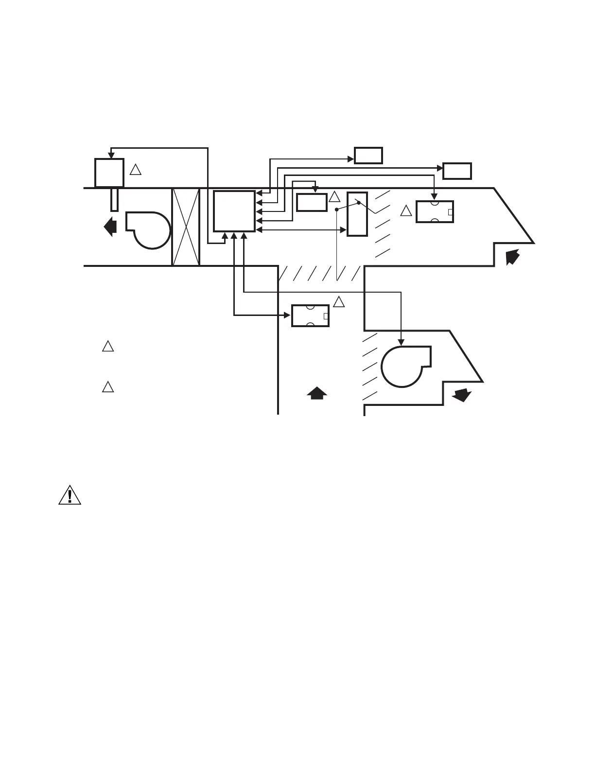
Fig. 4. Representative locations of connected economizer system devices.
Wiring
Electrical Shock or Equipment Damage Hazard.
Can shock individuals or short equipment
circuitry.
Disconnect power supply before installation.
IMPORTANT
1. All wiring must comply with applicable local codes,
ordinances and regulations.
2. Refer to Table 2 for a list of the wiring diagrams and
corresponding Figure numbers in this document.
3. All device inputs and outputs must be 24 Vac Class 2.
4. Ensure proper polarity of sensor connections.
Incorrect polarity negates the sensor signal.
Optional Applications
Heat Pump Changeover
(W7213, W7214 only)
In heat pump applications, the controller must have control of
the changeover valve. To provide the logic module with the
information necessary for proper information, there must be a
connection to the logic module O/B terminal. This terminal
alerts the logic module as to when the system operates in
cooling (the only time the economizer is used).
IMPORTANT
During heating applications with defrost, make sure to
break the connection to the economizer using an iso-
lation relay.
W7213 (CHANGEOVER TERMINAL B)
Connect the B terminal according to the following details:
— 24V power to B: System is in heating mode.
— No power to B: System is in cooling mode.
W7214 (CHANGEOVER TERMINAL O)
Connect the O terminal according to the following details:
— 24V power to O: System is in cooling mode.
— No power to O: System is in heating mode.
DISCHARGE
AIR SENSOR
C7046A
DIRECT
EXPANSION
COIL
ENTHALPY
SENSOR
C7232
ENTHALPY
SENSOR
RETURN AIR
OUTDOOR
AIR
C7150B
MIXED AIR
SENSOR
COMMERCIAL
THERMOSTAT
FOR DIFFERENTIAL ENTHALPY, THE TWO C7400
ENTHALPY SENSORS ARE CONNECTED TO THE
ECONOMIZER LOGIC MODULE—ONE
IS MOUNTED IN RETURN AIR, AND THE OTHER IS
MOUNTED IN OUTDOOR AIR.
USE EITHER MIXED AIR SENSOR OR DISCHARGE
AIR SENSOR, NOT BOTH.
M19547C
1
1
1
2
2
2
HONEYWELL
ACTUATOR
W7212,
W7213,
W7214
DCV
SENSOR
EXHAUST AIR
DISCHARGE
AIR
INDOOR
FAN
EXHAUST
FAN
C7400
C7400
 Loading...