Installing the XLS-REL
1.16 XLS-REL Technical Reference Manual
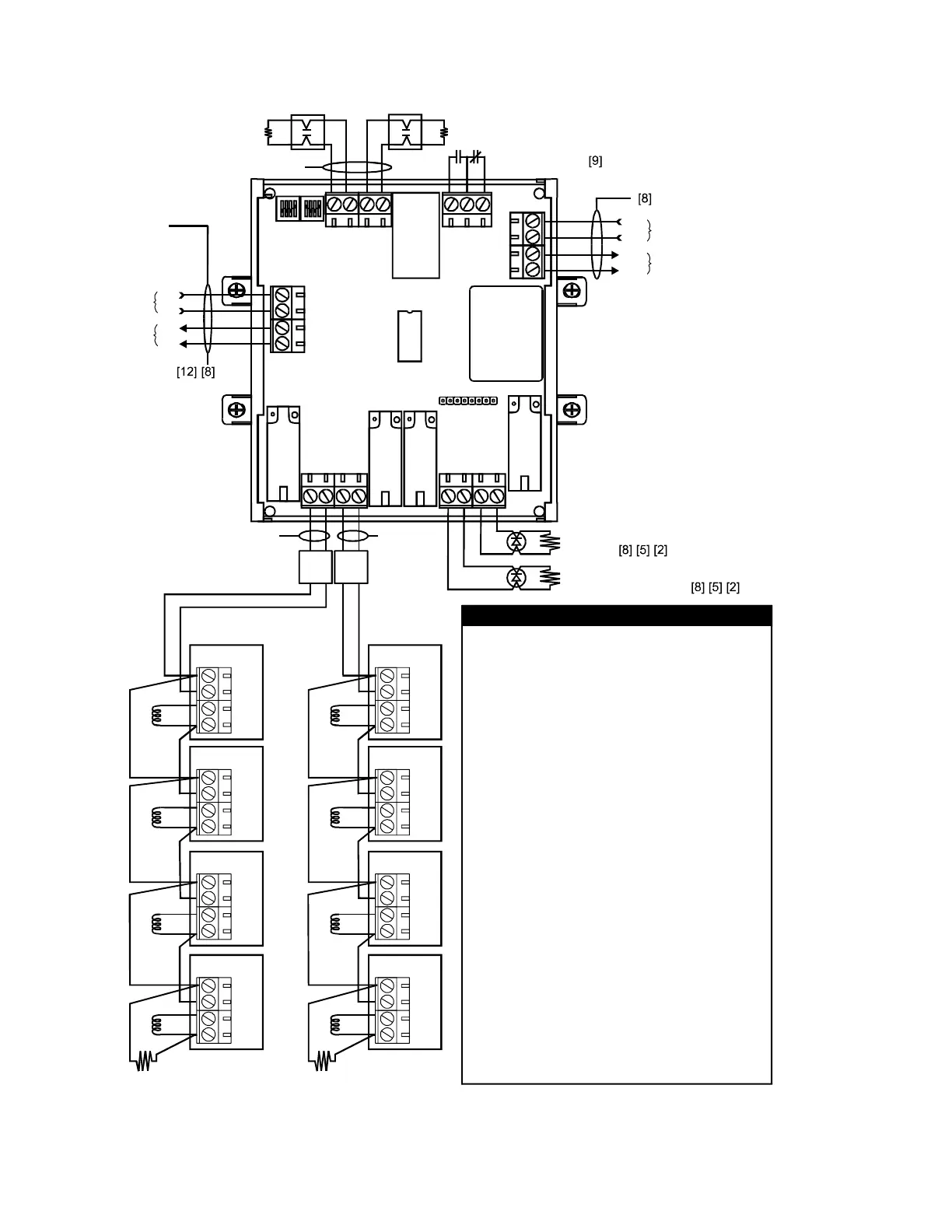
Figure 1-8: XLS-REL wiring
TB3 TB2
TB6
TB4 TB5
TB1
First alarm output
In
Out
+
_
+
_
+
24 Vdc in
24 Vdc out
Prerelease circuit 2
(steady)
Prerelease circuit 1
(pulsed 15/60/Steady)
Releasing Module
+
_
+
_
+
_
+
_
+
_
RELEASE023.CDR
4
3
2
1
3213214
4
3
2
1
3214 3214
Class A
Signature
Data
Circuit
Manual release circuit
[5]
Abort circuit
[5]
[8]
[1] Four RELA-EOLs per circuit, max.
[2] Class B, 24 Vdc output
[3] Class B, normally-open manual release station
[4] Class B, normally-open abort station
[5] Listed 47 k EOL resistor
[6] Listed 24 Vdc n
valve wiring is not supervised for wire-
to-wire shorts. Run the connection to the valve
in conduit within 20 feet of the RELA-EOL
Solenoid Polarizing Relay.
[7]
[8] Supervised and power-limited.
[9] P
W
onpolarized valve. The releasing
solenoid
Polarity of circuit shown in supervisory state. On
alarm, polarity reverses.
ower-limited when connected to a power-
limited source. If nonpower-limited, maintain 1/4
inch (6.4 mm) separation. Otherwise, use FPL,
FPLR, or FPLP in accordance with the National
Electric Code (NEC). Destroy power-limited
markings.
[10] Listed service disconnect station
[11] Not included in preaction or deluge sprinkler
systems
[12] Ten Releasing Modules per loop, max.
13 Installations, which include other wiring, require
FPL, FPLR, FPLP, or equivalent NEC-approved
wiring for all power-limited wiring.
Notes
[3] [4]
1
2
3
4
RELA-EOL
[6]
[5]
1
2
3
4
RELA-EOL
1
2
3
4
RELA-EOL
1
2
3
4
RELA-EOL
[2][1]
Release
circuit 2
[6]
[6]
[6]
[10] [10]
1
2
3
4
RELA-EOL
[6]
[5]
1
2
3
4
RELA-EOL
1
2
3
4
RELA-EOL
1
2
3
4
RELA-EOL
Release
circuit 1
[6]
[6]
[6]
[8][7][2][1] [8][7]
[11] [11]
[11] [11]
 Loading...