13 / 19
4.1 Fitting the Actuator to the Valve
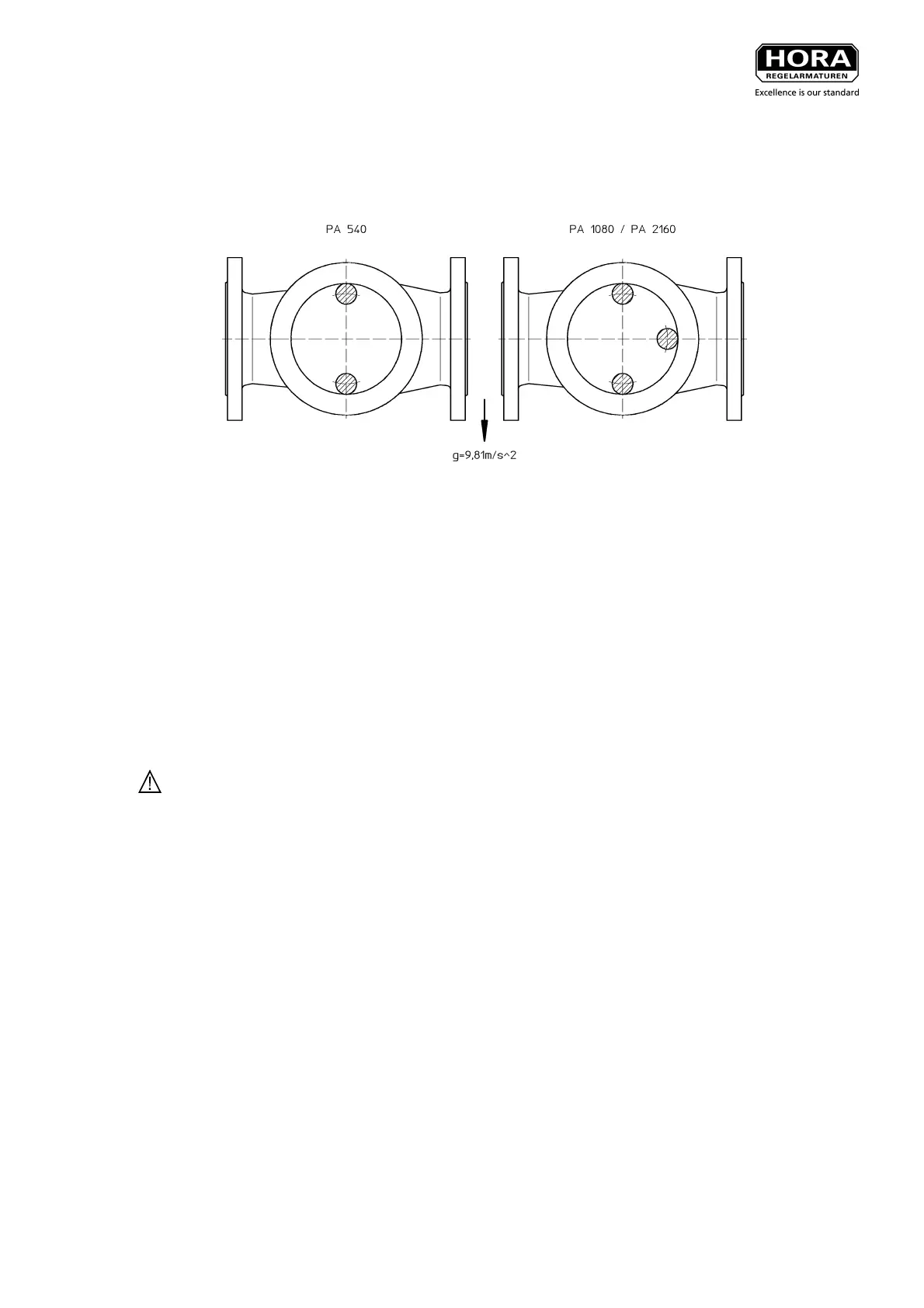
For installation at an angle, fit the actuator so that the maximum resistance force is achieved by the position
of the supports (see Fig. 5).
Fig. 5: Position of Supports for Horizontal Installation
Supporting the actuator weight is recommended starting from an angle of 30° from the vertical. This applies
in particular if vibrations in the pipework system are anticipated.
Installation procedure:
• Bring the valve cone spindle into the lower seat position.
• Mount the actuator without tightening the nuts and screws for fixing to the valve crossbar.
• Connect the control air pipe to the actuator (see Chapter 4.3)
• If there is a manual control, fit the stroke indicator on the housing (36 & 39) between the grooves on the
manual control supports (43).
• Set the required starting point (e. g. 1.1 bar) for an actuatror with SC operation.
For an actuator with SO operation, extend the stroke until the actuator spindle comes to a standstill just
before the valve spindle.
Danger Ensure that compressed air cannot escape accidentally from the actuator. A pressure
drop in the actuator can cause prestress between the valve and actuator spindle (1) and ejection
of the coupling (22) (if the cheese-head screws (23) have been removed).
Note: With actuators with manual control, the actuator spindle (1) can also be brought into the correct
position via the manual control.
• Connect the valve and actuator spindle (1) via the coupling (22 & 23) in the respective actuating position,
whereby it should be ensured that the threads are fully engaged and that the stroke indicator arrow
points to the lowest mark on the stroke indicator plate when the actuator is closed.
• Now tighten the nuts and screws to fix the actuator to the valve crossbar.
 Loading...