7 / 14
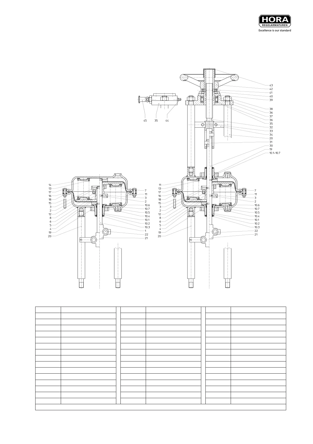
3.4 Sectional drawing with parts list
SC SO SC SO
Picture 2: Actuator type PA-N 160 SC and SO without and with manual positioning (structure identical
for PA-N 280)
Position Designation Position Designation Position Designation
1 Spindle 10.7 O-ring 31 Grooved clamping pin
2 Ring divided 11 Cover bottom 32 Leadscrew
3 Membrane disc 12 Spring centring sheet 33 Hexagonal screw
4 Membranes * 13 Pressure spring 34 Rotary guard
5 Plate 14 Cover top 35 Bridge
6 Axial clamping screw 15 Hexagonal screw 36 Axial needle ring
7 Tension nut 16 Disk 37 Threaded bush
8 Threaded pin 17 Hexagonal screw 38 Hexagonal nut
10 Guide, complete * 18 Hexagonal nut 39 Bridge lid
10.1 Guide 19 Groove nut 40 Cylinder screw
10.2 Socket 20 Column 41 Threaded pin
10.3 Scraper 21 Coupling 42 Hand wheel
10.4 Support ring 22 Cylinder screw 43 Flap
10.5 Square ring 44 Grease nipple
10.6 Disk 30 Spindle 45 Locking bolt
* Spare Parts
Table 3: Parts list for picture 2
 Loading...