6 / 14
3.2 Function and mode of operation
By means of the pneumatic actuator pneumatic control signals are converted into a shearing movement. The
necessary reaction force is generated by the pressure springs on membrane plate.
In case of air failure the actuator is reset into the initial position through the spring force.
The operating mode of the drive, spring opens – air closes (SO) or air opens – spring closes (SC) is
achieved depending on the installation of the springs. For actuators already installed in systems the
operating mode can be changed with simple tools without additional parts.
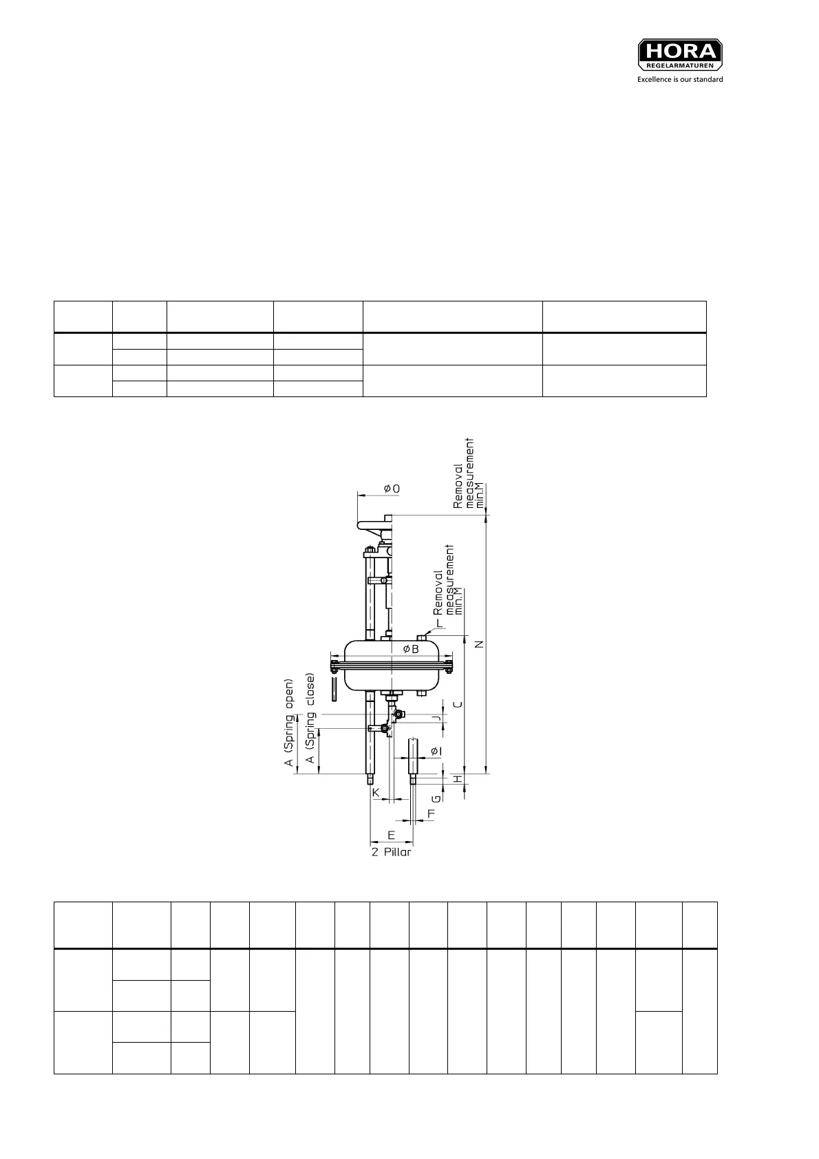
3.3 Dimension drawing
Actuator
type
Stroke
[mm] {in}
Total volume
[dm³] {cu.in}
Stroke volume
[dm³] {cu.in}
Weight without manual positioning
[kg] {lb}
Weight with manual positioning
[kg] {lb}
10 {0,39} 0,34 {20,75} 0,16 {9,76}
PA-N 160
20 {0,78} 0,5 {30,51} 0,32 {19,52}
5,8 {12,8} 9,1 {20,1}
20 {0,78} 1,04 {63,46} 0,56 {34,17}
PA-N 280
30 {1,18} 1,32 {80,55} 0,84 {51,26}
12,9 {28,4} 16,2 {35,7}
Table 1: Volumes and weights (total volume equals stroke volume + air volume with relaxed springs)
Picture 1: Actuator type PA-N 280 SC and SO without and with manual positioning (structure identical
for PA-N 160)
Actuator
type
Operating
mode
A
(1)
[mm]
{in}
ØB
[mm]
{in}
C.
[mm]
{in}
E
[mm]
{in}
FG
[mm]
{in}
H
[mm]
{in}
ØI
[mm]
{in}
J
[mm]
{in}
KLM
[mm]
{in}
N
[mm]
{in}
ØO
[mm]
{in}
FS
107
{4,21}
PA-N 160
FÖ
127
{5,0}
202
{7,95}
291
{11,46}
573
{22,56}
FS
107
{4,21}
PA-N 280
FÖ
137
{5,39}
284
{11,1
8}
323
{12,72}
100
{3,94}
M12
15
{0,59}
25
{0,98}
20
{0,79}
19,5
{0,77}
M10
NPT
¼ /
G ¼
200
{7,87}
605
{23,82}
160
{6,3}
Table 2: Dimensions in pressure-free status for picture 1
(1)
at spring range beginning
 Loading...