9 / 14
4.1 Installation of the actuator onto the valve
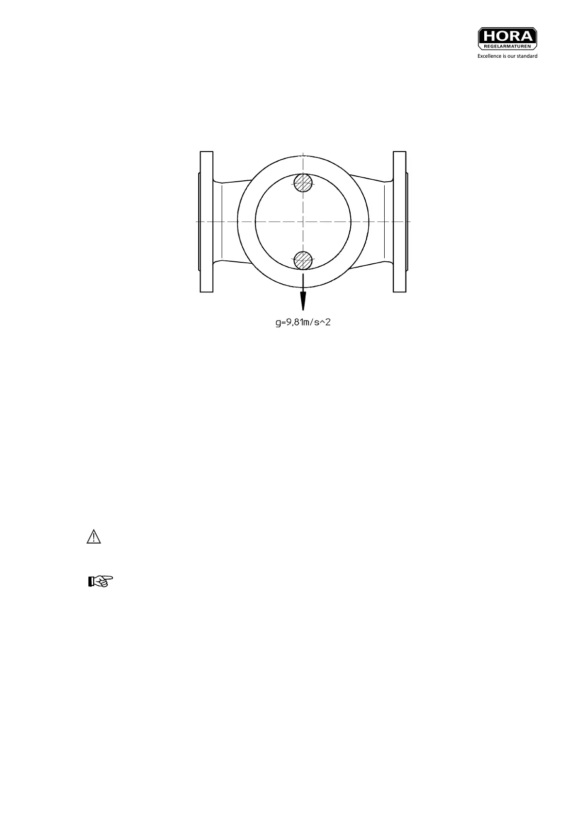
For diagonal installation position the actuator must be installed in a way that the position of the columns
generate the maximum resistance torque (see picture 3).
Picture 3: Position of the columns for horizontal installation
From a diagonal position of 30° of a vertical position it is recommended to support the actuator weight. This
is important if vibration of the pipe system is likely.
In the following installation is carried out:
• Bring the cone spindle of the valve into the lower fitting position.
• Place the actuator on without tightening the nuts (on column 20) for fastening tightly.
• Connect control air conduit to the actuator (see chapter 4.3)
• if a manual positioning exists, the turning safeguard (34) must be moved with the manual wheel (42) to
zero position (marked by a sign on column 20).
• For a drive with operating mode SC, set the desired starting point (e.g. 1.1 bar).
For a drive with operating mode SO, drive out the stroke until the actuator spindle comes to a halt closely
before the valve spindle.
Danger: Please ensure that no compressed air can unintentionally escape from the actuator.
A pressure drop in the actuator may lead to a pre-tension between the valve and the actuator
spindle (1), blowing off the coupling (21) (when cylinder screws (22) are removed).
NOTE: For drives with manual positioning the actuator spindle (1) can also be brought into fitting
position via manual positioning.
• In the respective actuator position, connect valve and actuator spindle (1) by means of coupling (21 and
22), observing that the threads fully catch.
• No tighten the nuts that fasten the columns (20) on the valve.
• Put manual positioning (if available) into 0 position. Turn the manual wheel to the extend that the turning
safeguard (34) is at the same level as the marking (sign on column 20).
 Loading...