Page 3
CONTROLLER OVERVIEW
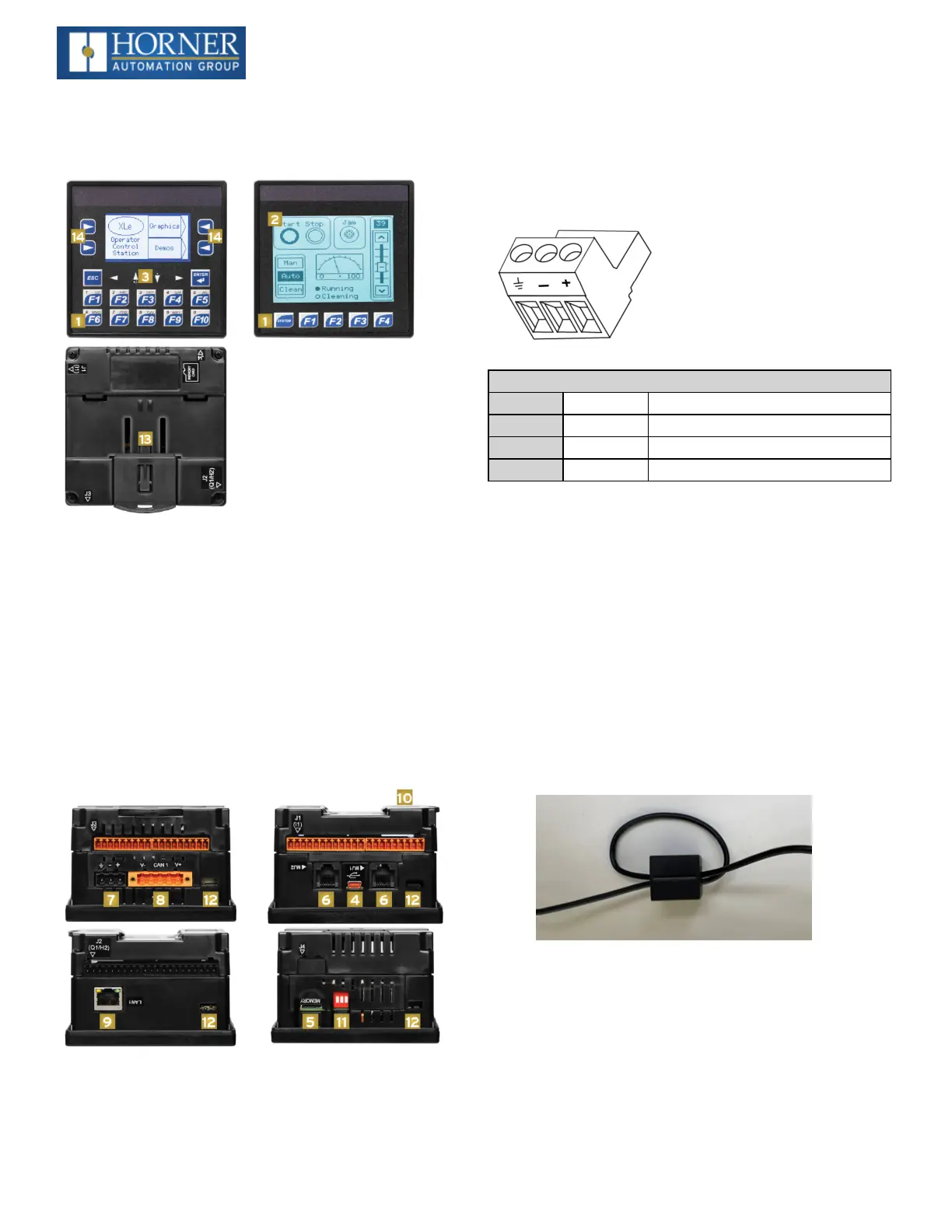
Overview of XLE and XLT
1. FunctionKeys
2. Touchscreen
3. NavigationKeys
4. USBMini-BPort
5. HighCapacitymicroSDSlot
6. RS232/RS485SerialPorts(2)
7. Wide-RangeDCPower
8. CANPort
9. EthernetLANPort(XLEeandXLTeonly)
10. OptionalBuilt-InI/O(Models2-6only)
11. ConfigurationSwitches
12. MountingClipLocations
13. DINRailClip
14. Softkeys
NOTE:SeePrecaution#12onaboutUSBandgrounding.
Power Wiring
NOTE:ThePrimaryPowerRangeis10VDCto30VDC.
Primary Power Port Pins
PIN Signal Description
1 Ground FrameGround
2 DC- InputPowerSupplyGround
3 DC+ InputPowerSupplyVoltage
DC Input / Frame
l
Solid/StrandedWire:12-24awg(2.5-0.2mm)
l
Striplength:0.28”(7mm)
l
Torque,TerminalHold-DownScrews:4.5–7in-lbs
(0.50–0.78N-m)
l
DC-isinternallyconnectedtoI/OV-,butisisolated
fromCANV-.AClass2powersupplymustbeused.
Power Up
1. OPTION:Attachferritecorewithaminimumoftwo
turnsoftheDC+andDC-signalsfromtheDCsupply
thatispoweringthecontrollers.
2. Connecttoearthground.
3. Applyrecommendedpower.

 Loading...

