Wiring:Model 2
Page 6
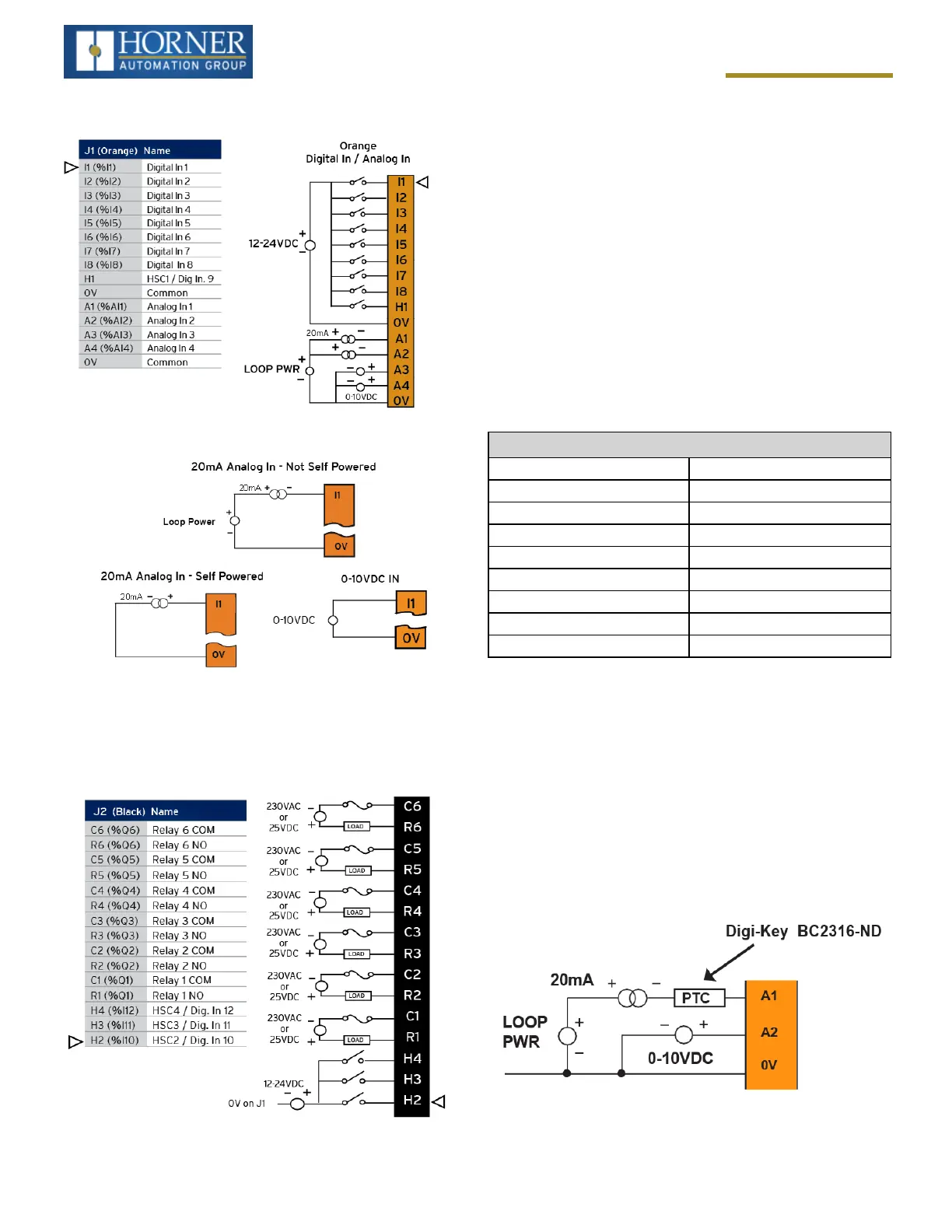
J1 Wiring - Digital In / Analog In
NOTE:The0Vterminalsareinternallyconnected.
J2 Wiring - Relay Out / Analog or
Digital In
Wiring Details
Solid/Stranded Wire:12-24awg(2.5-0.2mm2).
Strip Length:0.28”(7mm).
Torque, Terminal Hold-Down Screws:4.5–7in-lbs
(0.50–0.78N-m).
BUILT-IN I/O
TheI/OismappedintoOCSRegisterspace,inthreesep-
arateareas–Digital/AnalogI/O,High-SpeedCounterI/O,
andHigh-speedOutputI/O.Digital/AnalogI/Olocationis
fixedstartingat1,butthehigh-speedcounterandhigh-
speedoutputreferencesmaybemappedtoanyopen
registerlocation.
Digital and Analog I/O Functions
DigitalInputs %I1-12
Reserved %I13-32
ESCPAlarm n/a
DigitalOutputs %Q1-6
Reserved %Q7-24
AnalogInputs %AI1-4
Reserved %AI5-12
AnalogOutputs n/a
Reserved n/a
Analog Input Tranzorb Failure
AcommoncauseofAnalogInputTranzorbFailureonAna-
logInputsModel2,3,4&5:Ifa4-20mAcircuitisinitially
wiredwithlooppower,butwithoutaload,theanaloginput
couldsee24VDC.Thisishigherthantheratingofthetran-
zorb.ThiscanbesolvedbyNOTconnectinglooppower
priortoloadconnection,orbyinstallingalow-costPTCin
seriesbetweentheloadandanaloginput.

 Loading...

