Page 8
DIMENSIONS & INSTALLATION
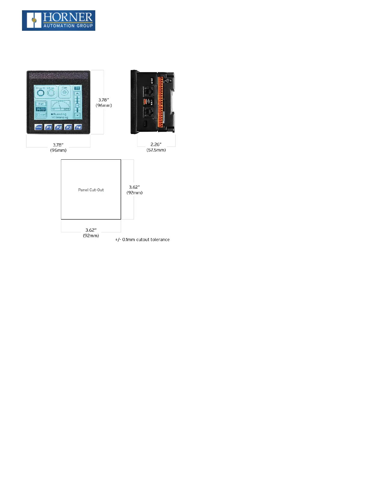
Dimensions & Panel Cutout
Installation Information
l
TheXLE/XLTutilizesaclipinstallationmethodto
ensurearobustandwatertightsealtotheenclosure.
Pleasefollowthestepsbelowfortheproperinstall-
ationandoperationoftheunit.
l
ThisequipmentissuitableforClassI,Division2,
GroupsA,B,CandDornon-hazardouslocations
only.
l
Digitaloutputsshallbesuppliedfromthesame
sourceastheoperatorcontrolstation.
l
JumpersonconnectorJP1shallnotberemovedor
replacedwhilethecircuitisliveunlesstheareais
knowntobefreeofignitableconcentrationsofflam-
mablegasesorvapors.
l
WARNING-TheUSBportsareforoperationalmain-
tenanceonly.Donotleavepermanentlyconnected
unlessareaisknowntobenon-hazardous.
Installation Procedure
1. Carefullylocateanappropriateplacetomountthe
XLE/XLT.Besuretoleaveenoughroomatthetopof
theunitforinsertionandremovalofthemicroSD™
card.
2. Carefullycutthehostpanelperthediagram,cre-
atinga92mmx92mm+/-0.1mmopeningintowhich
theXLE/XLTmaybeinstalled.Iftheopeningistoo
large,watermayleakintotheenclosure,potentially
damagingtheunit.Iftheopeningistoosmall,the
OCSmaynotfitthroughtheholewithoutdamage.
3. Removeanyburrsandorsharpedgesandensure
thepanelisnotwarpedinthecuttingprocess.
4. RemoveallRemovableTerminalsfromthe
XLE/XLT.InserttheXLE/XLTthroughthepanel
cutout(fromthefront).Thegasketmustbebetween
thehostpanelandtheXLE/XLT.
5. Installandtightenthefourmountingclips(provided
inthebox)untilthegasketformsatightseal(NOTE:
Maxtorque0.8to3Nm,or7-10in-lbs).
6. ReinstalltheXLE/XLTI/ORemovableTerminal
Blocks.Connectcommunicationscablestothe
serialport,USBports,Ethernetport,andCANport
asrequired.
Battery Maintenance
TheXLE/XLTusesareplaceablenon-rechargeable3VLith-
iumcoincellbattery(CR2450)toruntheReal-TimeClock
andtokeeptheretainedregistervalues.Thisbatteryis
designedtomaintaintheclockandmemoryfor7to10
years.PleasereferenceMAN0878providinginstructions
onhowtoreplacethebattery.

 Loading...

