Page 7
COMMUNICATIONS
Serial Communication
MJ1 Wiring
RS-232withfullhandshakingorRS-485half-
duplex
RS-485terminationviaswitches;biasingviasoft-
ware
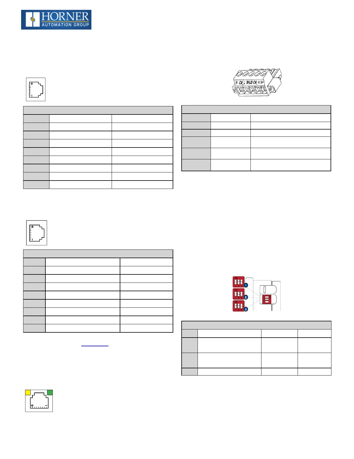
MJ1 Pins
PIN SIGNAL DIRECTION
8 TXD OUT
7 RXD IN
6 0V GROUND
5 +5V@60mA OUT
4 RTS OUT
3 CTS IN
2 RX-/TX- IN/OUT
1 RX+/TX+ IN/OUT
MJ2 Wiring
RS-232orRS-485halforfull-duplex,software
selectable
RS-485terminationviaswitches;biasingvia
software
MJ2 Pins
PIN SIGNAL DIRECTION
8 232TXD OUT
7 232RXD IN
6 0V GROUND
5 +5V@60mA OUT
4 485TX- OUT
3 485TX+ IN
2 485RX-orRX/TX- INorIN/OUT
1 485RX+orRX/TX+ INorIN/OUT
NOTE:Attachoptionalferritecorewithaminimumoftwo
turnsofserialcable.
Ethernet
Green LED indicates link-whenillu-
minated,datacommunicationisavailable.
Yellow LED indicates activity-when
flashing,dataisintransmission.
CAN Communications
CAN Pin Assignments
PIN SIGNAL DESCRIPTION
1 V- CANGround–Black
2 CN_L CANDataLow–Blue
3 SHLD ShieldGround–None
4 CN_H CANDataHigh–White
5 V+(NC) NoConnect–Red
l
Solid/Stranded Wire:12-24awg(2.5-0.2mm).
l
Strip Length:0.28”(7mm).
l
Lockingspring-clamp,two-terminatorspercon-
ductor.
l
Torque, Terminal Hold-Down Screws:4.5–7in-
lbs(0.50–0.78N-m).
l
V+pinisnotinternallyconnected,theSHLDpinis
connectedtoEarthgroundviaa1MΩresistorand10
nFcapacitor.
Dip Switches
DIP Switches
PIN NAME FUNCTION DEFAULT
1
MJ1RS-485
Termination
ON=Ter-
minated
OFF
2
MJ2RS-485
Termination
ON=Ter-
minated
OFF
3 Bootload AlwaysOff OFF
TheDIPswitchesareusedtoprovideabuilt-intermination
toboththeMJ1portandMJ2portifneeded.Theter-
minationfortheseportsshouldonlybeusedifthisdeviceis
locatedateitherendofthemultidrop/daisy-chainedRS-
485network.

 Loading...

