Page 19 Electrical Requirements
9. Replace the control box cover and securely tighten the fastening screws. Close and secure the equipment
compartment door.
WARNING: Fill the spa with water before turning on the power.
Once your spa has been filled with water, turn it on and test all of the circuit breakers.
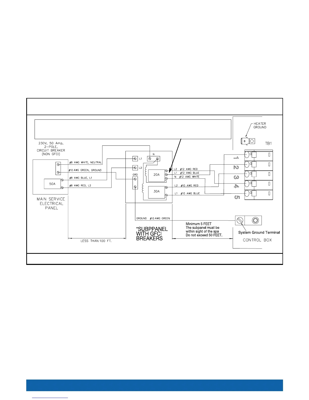
NOTE: If both breakers immediately trip, verify that the #12 AWG WHITE neutral wire is connected from TB-1 terminal 5
to the L1 (load neutral) terminal of the 20 amp subpanel breaker. Each breaker should be tested prior to each use. Here’s
how:
1. Push the “TEST” button on each GFCI breaker, and observe it click OFF.
2. Wait 30 seconds, then push the breaker switch to the OFF (down) position (to ensure that it has completely
disengaged), then push the breaker switch to the ON (up) position. If you don’t wait 30 seconds, the spa’s power
indicator may continue to blink–try again.
If any of the GFCI breakers fails to operate in this manner, your spa may have an electrical malfunction, and you may be
at risk of electrical shock. Turn off all circuits and do not use the spa until the problem has been corrected by an
authorized service agent.
WARNING: Removing or bypassing any GFCI breaker will result in an unsafe spa and will void the spa’s warranty.
IMPORTANT: Should you ever find the need to move or relocate your Hot Spring
®
Spa, it is essential that you
understand and apply these installation requirements. Your Hot Spring
®
Spa has been carefully engineered to provide
maximum safety against electric shock. Remember, connecting the spa to an improperly wired circuit will negate many of
its safety features.
NOTE: Long wiring runs may require larger-gauge wire than stated. We recommend using a maximum 3% voltage drop
when calculating wire gauge requirements.
Landmark
®
(Model S), Grandee
®
(Model G) and Vanguard
™
(Model V)
230 volt permanently connected models
WARNING! The exact physical location of the terminals on the GFCI
breaker will vary between manufacturers. Connecting the hot wire to the
neutral terminal will cause irreversible damage to the control box.
*PROVIDED WITH SPA. NOTE: ALL WIRING SHOULD BE COPPER.
NOTE: The wire connections to GFCI breakers are for reference only. Always ensure the white neutral wire is connected to the load neutral of the 20 amp breaker.
** Refer to NEC 250-122 (table)
**