I/O BOARD LED
40 SERVICE MANUAL
REVISION 04/19, SW: 3.51
I/O BOARD LED
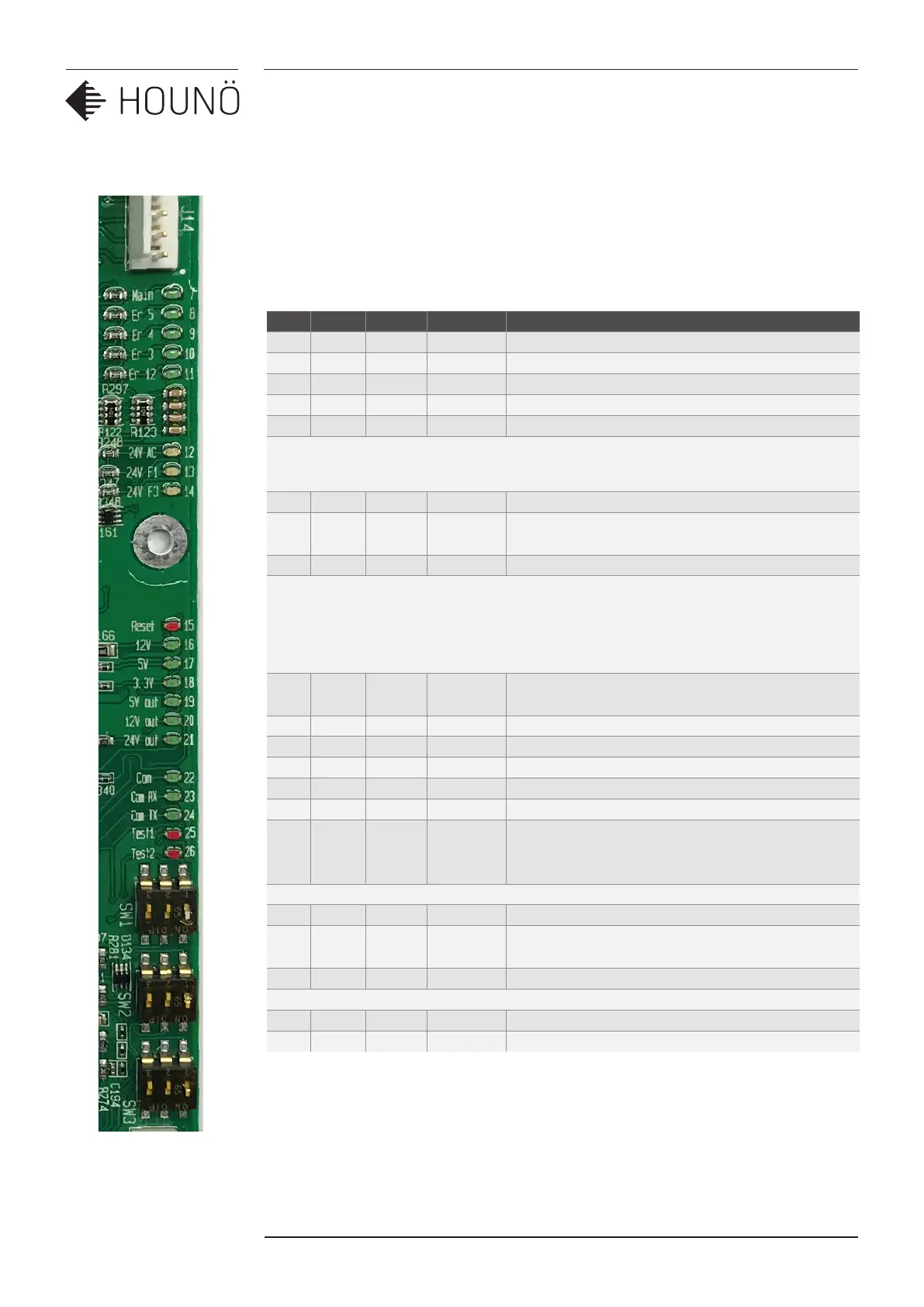
Description, connection of the dierent led on the I/O to help under stand the dierent
functions of the I/O board
No Colour Volt Plug. Pin DESCRIPTION
7 Green Main Voltage to main contator OK.
8 Green ER5 J14 Pin 5 Voltage fan alarm switch OK.
9 Green ER4 J14 Pin 4 Voltage oven overheating switch OK.
10 Green ER3 J14 Pin 3 Voltage from steam generator switch OK.
11 Green Er12 J14 Pin 2 Voltage from SSR overheating switch
12 Yellow 24V F2 J10 Fuse F2 Power supply to I/O board.
13 Yellow 24V F1 J2 Pin
1,3,5
Fuse F1 is OK.
14 Yellow 24V F3 J8 Pin 3,6 Fuse F3 is OK.
15 Red Reset The I/O board is in a reset mode (flashes only at
start).
16 Green 12V The internal 12V is present.
17 Green 5V The internal 5V is present.
18 Green 3,3V The internal 3,3V is present.
19 Green 5V out J1 Pin 13 External 5V for door sensor and RPM sensor.
20 Green 12V J1 Pin 15 External 12V for the ClimaOptima sensor
21 Green 24V J18 pin 1
J19 Pin 1
J20 Pin 1
External 24V voltage for the gas fan interface.
This option is only present on I/O board
P/N 30900015
22 Green Com Slow flashing when I/O communicates with the CPU
23 Green Com
RX
Fast flashing when data received from CPU
24 Green Com TX Fast flashing when data is send to the CPU
25 Red Test 1 Lights when communication is not working
26 Red Test 2 Lights shortly under start
 Loading...