Removal and Replacement Procedures
Maintenance and Service Guide 5–33
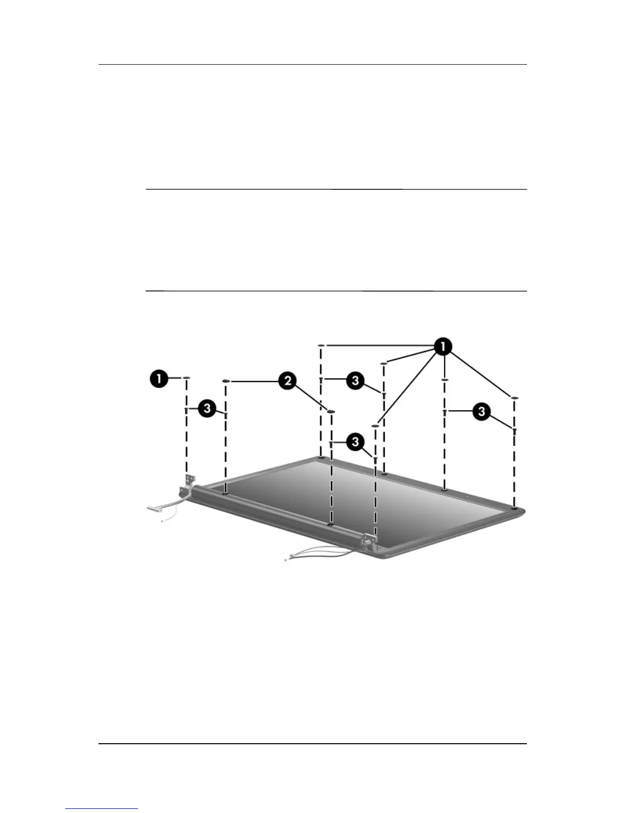
10. Remove the following:
1 Six rubber screw covers
2 Two rubber screw covers
3 Eight Phillips PM2.5×7.0 screws
✎
There are two different sizes of display bezel rubber screw
covers. The thicker covers 2 should be installed in the bottom
center screw holes.
The display rubber screw covers are included in the Display
Screw Kit, spare part number 417105-001.
Removing the Display Bezel Screws