EasyManuals Logo

HP 14 User Manual

HP 14
146 pages
To Next Page IconTo Next Page
To Previous Page IconTo Previous Page
Page #71 background imageLoading...
Page #71 background image
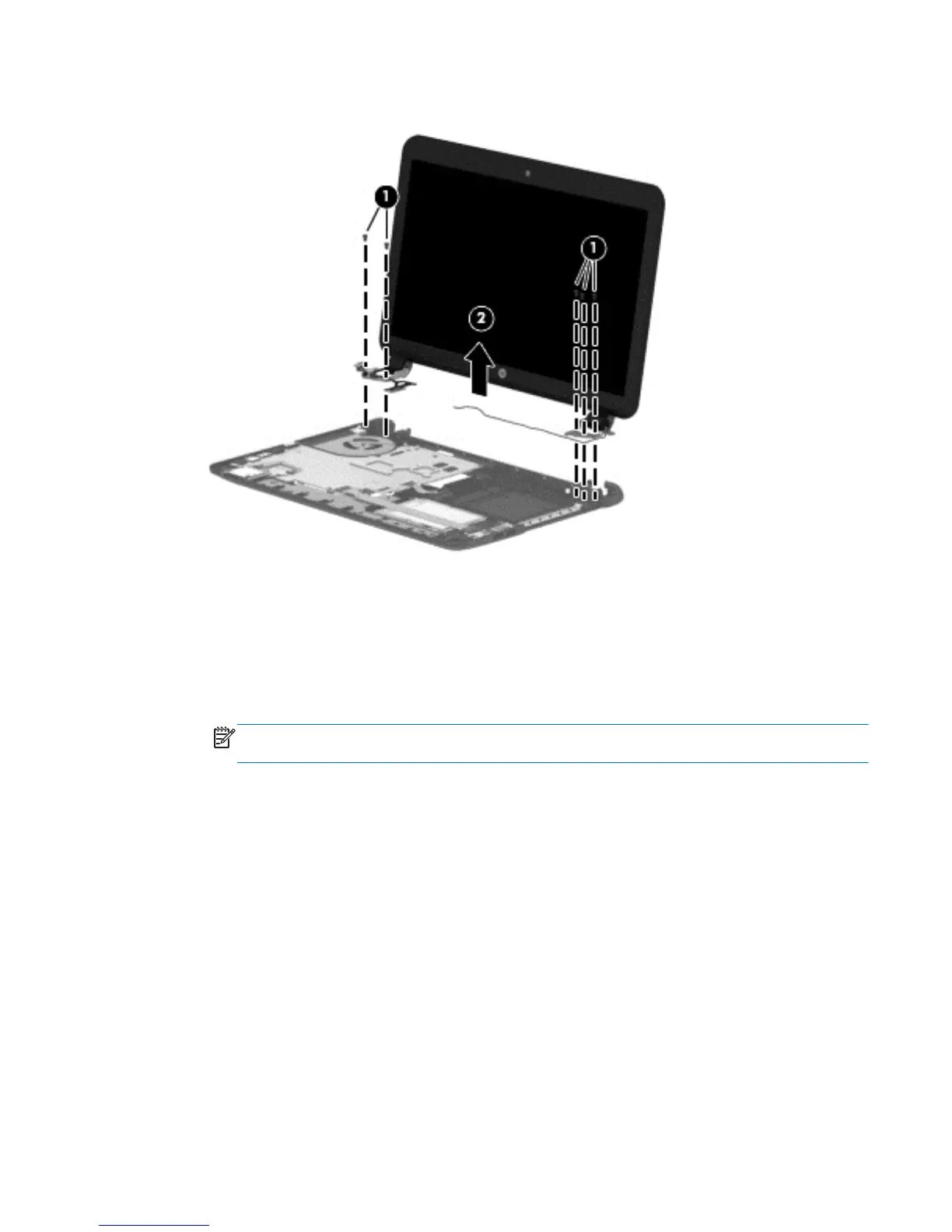
5. Remove the display assembly (2).
If it is necessary to replace any of the display assembly subcomponents:
1. To remove the display bezel:
a. Remove the two Mylar screw covers (1) and the two Phillips PM2.5×4.5 screws (2) that secure the
display bezel to the display assembly. The Mylar screw covers are included in the Rubber Kit, spare
part number 747256-001 for HP 14 and Compaq 14 models, 749021-001 for HP 240 models, and
753184-001 for HP 245 models.
NOTE: In this procedure, the display will NOT be connected to the computer, as shown in the
following image.
Component replacement procedures 63

Table of Contents

Questions and Answers:

Question and Answer IconNeed help?

Do you have a question about the HP 14 and is the answer not in the manual?

HP 14 Specifications

General IconGeneral
TypeOriginal
Ink typePigment-based ink
Compatibility-
Printing colorsBlack
Print technologyInkjet printing
Quantity per pack1 pc(s)
Cartridge capacityHigh (XL) Yield
Storage temperature (T-T)0 - 60 °C
Operating temperature (T-T)15 - 35 °C
Weight and Dimensions IconWeight and Dimensions
Package typeBox
Package weight58.9 g

Related product manuals