2
4. Install the Switch Hardware (Continued)
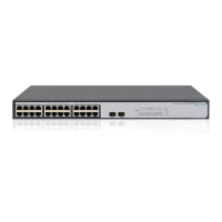
Wall (or Under-Table): A hardware kit for wall-mounting (or
under-table mounting) is included. Use a #1 Phillips (cross-
head) screwdriver and the 20-mm M4 tap screws (included).
For screw positions, see the mounting hole dimensions on
page 4. (Under-Table: After installation, a third screw may be
used to prevent switch movement.)
For wall-mounting, the network ports may face up or down.
Do not mount the switch with ventilation ducts facing up or
down. (See
“Safety Precautions” on page 3.)
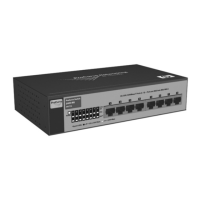
Rack Mounting: A special rack-mounting kit is included. Use a #1 Phillips (cross-head) screwdriver to attach the special
brackets to the switch using the eight 8-mm M4 screws. Then use the four number 12-24 screws to secure the brackets to the
rack.
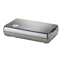
5. (Optional) Lock the Switch. Use a Kensington lock or similar device (not included) to physically secure the switch.
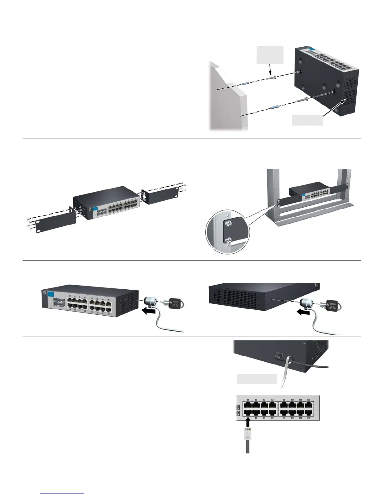
6. Power On the Switch.
Use the cable tie strap to secure the connection.
7. Connect Network Cables.
M-4 tap
screws
Ventilation